
Single-layer sub-wavelength reflective array phase modulation unit

A reflection array and phase modulation technology, which is applied to the structure of the radiating element, the antenna array that is energized separately, and the electrical elements, etc., can solve the problem that the reflection phase range is difficult to reach 360 degrees, affects the antenna radiation characteristics and broadband characteristics, and has different coupling effects. question

Pending Publication Date: 2020-12-11
BEIJING INST OF RADIO MEASUREMENT
View PDF7 Cites 5 Cited by
  • Summary
  • Abstract
  • Description
  • Claims
  • Application Information

AI Technical Summary

Problems solved by technology

Generally speaking, a reflectarray unit adjusts the reflection phase of the unit by changing one or several of its parameters. For a traditional reflectarray unit, this will cause changes in its peripheral dimensions, which in turn will lead to different positions in the array. The coupling effect between the units is different, which brings difficulties to the analysis of the reflection characteristics of the units
[0004] In summary, it is difficult to accurately consider the coupling between adjacent elements at different positions in the existing planar reflectarray antenna design, and the reflection phase range is difficult to reach 360 degrees, thus affecting the antenna radiation characteristics and broadband characteristics

Method used


Image

  • Single-layer sub-wavelength reflective array phase modulation unit
  • Single-layer sub-wavelength reflective array phase modulation unit
  • Single-layer sub-wavelength reflective array phase modulation unit

Examples


Embodiment Construction

[0029] The technical solutions in the embodiments of the present invention will be clearly and completely described below in conjunction with the accompanying drawings in the embodiments of the present invention. Obviously, the described embodiments are only part of the embodiments of the present invention, not all of them. Based on the implementation manners in the present invention, all other implementation manners obtained by persons of ordinary skill in the art without making creative efforts belong to the scope of protection of the present invention.

[0030] For the convenience of description, the descriptions involving "first", "second", etc. in the present invention are only set for the purpose of description, and should not be understood as indicating or implying their relative importance or implicitly specifying the number of indicated technical features. Thus, the features defined as "first" and "second" may explicitly or implicitly include at least one of these feat...


PUM

PropertyMeasurementUnit
frequencyaaaaaaaaaa
thicknessaaaaaaaaaa

Abstract

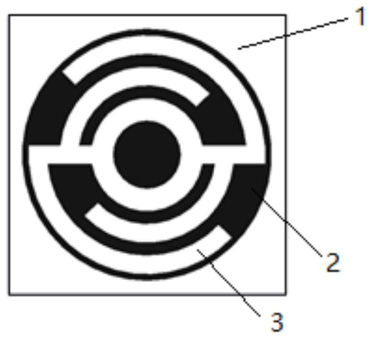
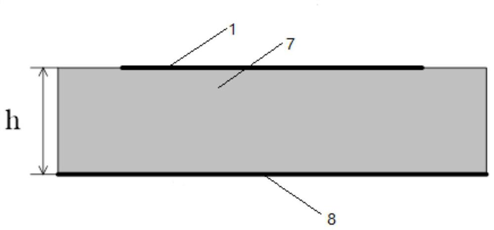
The invention provides a single-layer sub-wavelength reflective array phase modulation unit. The single-layer sub-wavelength reflective array phase modulation unit comprises a first branch part and asecond branch part, wherein one of the first branch part and the second branch part is hollow, the other one of the first branch part and the second branch part is solid, the surface where a hollowed-out part is located and the surface where a solid body is located form a complementary structure, and the first branch part comprises a middle part, a connecting part, a first branchknot part and thesecond branchknot part. When the phase modulation unit is used for designing a reflective array antenna, the peripheral size of the phase modulation unit is fixed, and the difference of coupling effects between adjacent units at different positions of the reflective array antenna is very small, so the characteristics of the units in the reflective array can be easily and accurately obtained, and the radiation performance of the reflective array antenna is improved.

Description

technical field [0001] The present invention relates to the technical field of antennas, and more specifically, to a single-layer sub-wavelength reflective array phase modulation unit. Background technique [0002] Planar reflectarray antenna is a relatively new form of high-gain antenna. It includes two parts: feed source and reflectarray. The reflectarray is composed of several reflective units. The feeder feeds the surface through empty feed. . This antenna has the advantages of light weight, simple processing, low cost, planar structure, foldable, and easy beamforming. However, this antenna also has the disadvantage of narrow bandwidth. Recent studies have shown that the use of sub-wavelength technology is an effective method to improve the bandwidth of planar reflectarrays. Due to the small period of the traditional sub-wavelength reflective unit, the range of the unit’s phase modulation parameters is limited, so its reflection phase range is difficult to reach 360 de...

Claims


Application Information

Patent Timeline
Patent Type & Authority Applications(China)
IPC IPC(8): H01Q3/34H01Q1/38H01Q1/52H01Q19/10H01Q21/06
CPCH01Q3/34H01Q1/38H01Q1/523H01Q19/10H01Q21/065
Inventor 薛飞
Owner BEIJING INST OF RADIO MEASUREMENT
Learn More