
Feeding equipment provided with pushing structure and used for machining of electronic parts

A technology of spare parts and push mechanism, which is applied in the direction of conveyors, mechanical conveyors, conveyor objects, etc., which can solve the problems of electronic parts rolling down, inconvenient adjustment of feeding angle, and lack of push structure, etc., so as to achieve flexible use Effect

Pending Publication Date: 2020-12-15
深圳市华博自动化设计有限公司
View PDF0 Cites 2 Cited by
  • Summary
  • Abstract
  • Description
  • Claims
  • Application Information

AI Technical Summary

Problems solved by technology

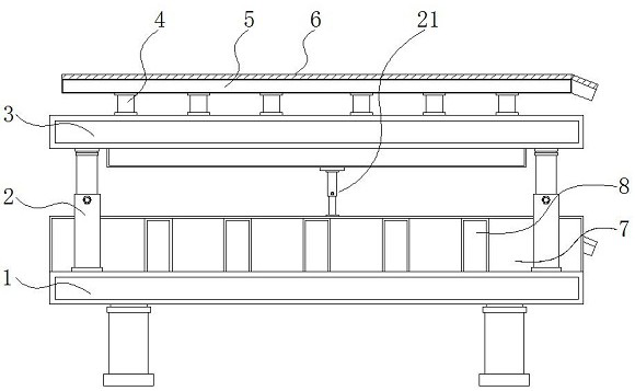
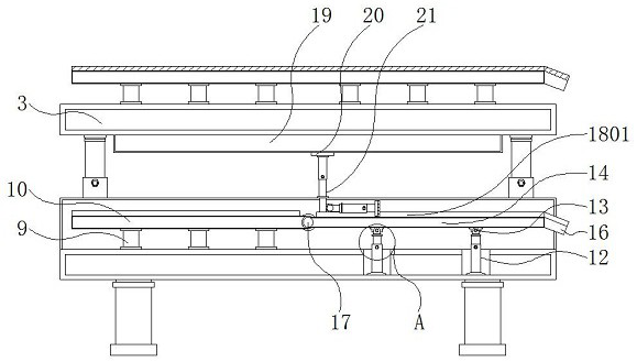
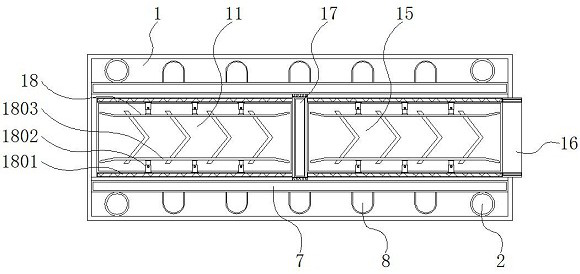
[0004] The purpose of the present invention is to provide a feeding device with a push structure for processing electronic parts, so as to solve the problem that the existing feeding device for processing electronic parts proposed in the background technology is inconvenient to adjust the feeding angle, and when feeding It is not flexible enough, and there is no corresponding push structure when loading materials, electronic parts may roll down due to gravity

Method used


Image

  • Feeding equipment provided with pushing structure and used for machining of electronic parts
  • Feeding equipment provided with pushing structure and used for machining of electronic parts
  • Feeding equipment provided with pushing structure and used for machining of electronic parts

Examples


Embodiment Construction

[0028] The technical solutions in the embodiments of the present invention will be clearly and completely described below in conjunction with the accompanying drawings in the embodiments of the present invention. Obviously, the described embodiments are only some of the embodiments of the present invention, not all of them. Based on The embodiments of the present invention and all other embodiments obtained by persons of ordinary skill in the art without making creative efforts belong to the protection scope of the present invention.

[0029] In the description of the present invention, unless otherwise stated, the meaning of "plurality" is two or more; the terms "upper", "lower", "left", "right", "inner", "outer" , "front end", "rear end", "head", "tail", etc. indicate the orientation or positional relationship based on the orientation or positional relationship shown in the drawings, and are only for the convenience of describing the present invention and simplifying the desc...


PUM


Abstract

The invention discloses feeding equipment provided with a pushing structure and used for machining of electronic parts, and relates to the technical field of machining of electronic parts. The feedingequipment comprises a base, a first conveying belt, a second conveying belt and a pushing mechanism; telescopic columns are installed on the two sides of the upper side of the base; a supporting plate is fixed to the upper sides of the telescopic columns; a fixing rod is connected to the upper side of the supporting plate; an installing frame is fixed to the upper side of the fixing rod; an upper-layer conveying belt is arranged on the inner side of the upper side of the installing frame; outer side plates are installed on the two sides of the outer part of the upper side of the base; rubberanti-collision strips are fixed to the outer walls of the outer side plates; and a connecting rod is fixed to the left side of the upper side of the base. The feeding equipment has the beneficial effects that through arrangement of a movable shaft, inclination adjustment of a second frame is facilitated, and the second frame is movably connected with electric hydraulic rods through movable connecting frames, so that the two groups of electric hydraulic rods can stretch out and draw back to adjust the inclination angle of the second frame, and different feeding requirements can be met.

Description

technical field [0001] The invention relates to the technical field of electronic spare parts processing, in particular to a feeding device with a push structure for electronic spare parts processing. Background technique [0002] Electronic components are part of electronic accessories and are the basis of electronic products. Electronic components are components of small machines and instruments. They are often composed of several parts and can be used in similar products. Since the 1990s Since the late 1990s, various electronic products that integrate the three major fields of computer, information and communication, and consumer electronics have begun to penetrate into family life extensively. During the processing of electronic parts, feeding equipment is required to load them. , The feeding equipment mostly adopts belt feeding, which is suitable for food, beverage, pharmaceutical, electronics, tobacco, chemical and other industries, so the feeding equipment is widely u...

Claims


Application Information

Patent Timeline
Patent Type & Authority Applications(China)
IPC IPC(8): B65G41/00B65G47/96B65G37/00B65G47/82B65G47/22B65G47/24
CPCB65G37/00B65G41/003B65G47/22B65G47/24B65G47/82B65G47/967
Inventor 陈静陈文康罗志雄
Owner 深圳市华博自动化设计有限公司
Learn More