Regeneration method and device of particle catcher

A particle trap and regeneration device technology, which is applied to the electronic control of noise reduction devices, exhaust devices, exhaust treatment devices, etc., can solve the problems of non-metallic parts burning, vehicle spontaneous combustion, etc., to improve efficiency and reduce spontaneous combustion. risk, avoiding the effect of overheating in the front cabin

Active Publication Date: 2020-12-15
CHERY AUTOMOBILE CO LTD
View PDF5 Cites 3 Cited by
  • Summary
  • Abstract
  • Description
  • Claims
  • Application Information

AI Technical Summary

Problems solved by technology

In the process of "burning" carbon particles, due to the operation of the engine, the temperature of the front compartment of the vehicle is very high, which may cause non-metallic components such as wiring harnesses and oil pipes to burn, so there is a risk of vehicle spontaneous combustion

Method used


Image

  • Regeneration method and device of particle catcher
  • Regeneration method and device of particle catcher
  • Regeneration method and device of particle catcher

Examples


Embodiment Construction

[0042] In order to make the purpose, technical solution and advantages of the present disclosure clearer, the implementation manners of the present disclosure will be further described in detail below in conjunction with the accompanying drawings.

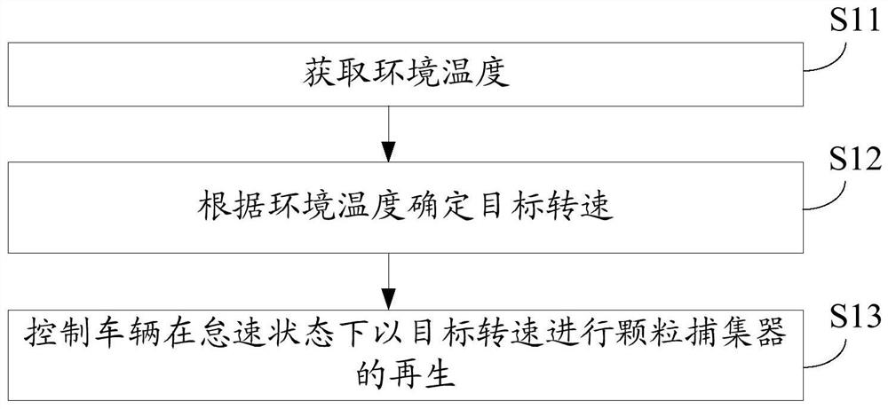
[0043] figure 1 It is a flowchart of a method for regenerating a particle trap provided by an embodiment of the present disclosure. Such as figure 1 As shown, the method includes:

[0044] In step S11, the ambient temperature is acquired.

[0045] In step S12, the target rotational speed is determined according to the ambient temperature.

[0046] Wherein, the target rotational speed is the rotational speed of the engine when the particulate filter is being regenerated.

[0047] In step S13 , the vehicle is controlled to perform regeneration of the particulate trap at the target rotational speed in an idling state.

[0048] By obtaining the ambient temperature, and then determining the regeneration of the particle filter accor...


PUM


Abstract

The invention provides a regeneration method and device of a particle catcher and belongs to the technical field of automobile tail gas treatment. The method comprises the steps that an environment temperature is obtained; a target rotating speed is determined according to the environment temperature, wherein the target rotating speed is the rotating speed of an engine during regeneration of the particle catcher; and a vehicle is controlled to conduct particle catcher regeneration at the target rotating speed in an idling state. The target rotating speed is determined according to the environment temperature, so that the engine can operate at a rotating speed relatively suitable for the current environment temperature, for example, when the environment temperature is low, the engine operates at a high rotating speed, the regeneration efficiency of the particle catcher is improved; and when the environment temperature is high, the engine operates at a low rotating speed, the temperatureof a front cabin of the vehicle is prevented from being too high, and therefore the risk of spontaneous combustion of the vehicle in the regeneration process of the particle catcher is reduced.

Description

technical field [0001] The disclosure relates to the technical field of automobile exhaust treatment, in particular to a method and device for regenerating a particle trap. Background technique [0002] A particulate filter is a filter installed in the engine exhaust system, including a gasoline engine particulate filter (Gasoline Particulate Filter, GPF) and an oil extraction machine particulate filter (Diesel Particulate Filter, DPF), which can filter particulate matter (mainly are carbon particles) before they are emitted into the atmosphere, thereby reducing the emission of soot produced by the engine. [0003] Since the particulate matter captured by the particulate filter accumulates in the particulate filter, the accumulation of particulate matter will cause an increase in engine back pressure, resulting in a decrease in engine performance, so it is necessary to periodically remove the particulate matter accumulated in the particulate filter. The process of removing ...

Claims


Application Information

Patent Timeline
Patent Type & Authority Applications(China)
IPC IPC(8): F01N3/023F01N9/00
CPCF01N3/023F01N3/0238F01N9/002F02D31/001Y02T10/40
Inventor 李树宇唐为义曹广富
Owner CHERY AUTOMOBILE CO LTD
Why Eureka
Try Eureka