Preventing surge

A surge margin, engine technology, applied in electromechanical devices, fuel control of turbine/propulsion devices, air transportation, etc., can solve problems such as seldom reference to optimal control strategies

Pending Publication Date: 2020-12-15
ROLLS ROYCE PLC
View PDF5 Cites 0 Cited by
  • Summary
  • Abstract
  • Description
  • Claims
  • Application Information

AI Technical Summary

Problems solved by technology

While many literatures present candidates for optimal physical implementations of such architectures, there is little reference to optimal control strategies to operate such configurations

Method used


Image

  • Preventing surge
  • Preventing surge
  • Preventing surge

Examples


Embodiment Construction

[0041] The invention is described in the context of a two-spool geared turbofan engine architecture. However, it will be apparent to those skilled in the art that the principles of the present invention can be applied to other engine types, including gas turbines having two or more slide valves, such as direct drive turbofans, turboprops, or open rotor engines .

[0042] figure 1 and figure 2

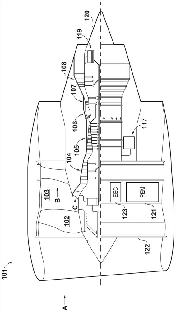
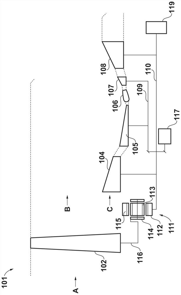
[0043] The general arrangement structure of the engine 101 of aircraft is in figure 1 is shown in the equivalent block diagram of its main components in figure 2 shown in .

[0044] In this embodiment, the engine 101 is a turbofan and thus includes a ducted fan 102 which receives intake air A and generates two streams: a bypass flow B axially through a bypass duct 103 and a flow B into the core gas turbine. core flow C.

[0045] The core gas turbine includes a low pressure compressor 104 , a high pressure compressor 105 , a combustor 106 , a high pressure turbine 107 and a l...


PUM


Abstract

The invention discloses a gas turbine engine for an aircraft, and the gas turbine engine 101 comprises a high-pressure (HP) spool comprising an HP compressor 105 and a first electric machine 117 driven by an HP turbine 107; a low-pressure (LP) spool comprising an LP compressor 104 and a second electric machine 119 driven by an LP turbine 108; a combustor 106; an electrical energy storage unit 305;and an engine controller 123 configured to: in response to receipt of a request for an increased electrical power supply by the engine (dPD) within a requested timeframe (dt), evaluating a current HPcompressor surge margin (dRH/RH) and a current LP compressor surge margin (dRL/RL) based on the operating points thereof; in response to evaluating that one or more of the HP compressor 105 and the LP compressor 104 has insufficient surge margin to facilitate a change of electrical power supply at a requested rate (dPD/dt), meeting the requested electrical power demand using the electrical energystorage unit 305 whilst increasing fuel flow to the combustor 106 to accelerate the engine 101.

Description

technical field [0001] The present disclosure relates to gas turbine engines. Background technique [0002] Gas turbine engines having electric machines capable of operating both as motors and generators are known, such as those used in more electric aircraft. While such engines may include multiple such motors for redundancy, they are coupled to only one of the spool valves. For example, one known configuration includes such a motor coupled to a high pressure spool valve of a dual spool turbofan. Another configuration includes such a motor coupled to the medium pressure spool of a three spool turbofan. [0003] The problem with such a configuration is that, for a given power demand, there is no choice but to provide power from a single spool valve in the engine. Therefore, turbomachinery must be designed to accommodate all possible electrical demands over the entire operating range, which inevitably leads to trade-offs. [0004] Therefore, it has been proposed to includ...

Claims


Application Information

Patent Timeline
Patent Type & Authority Applications(China)
IPC IPC(8): F02C6/00F02C9/56
CPCF02C6/00F02C9/56F05D2220/76F05D2270/101F02C7/36H02J2310/44F01D15/10H02J3/32H02J7/0048Y02T50/60Y02T50/50F02C7/32F02C9/16F02C9/26F02C9/48F04D27/02F04D27/0261F04D27/0284F05D2270/023H02K7/1823F02C9/28F02C9/42
Inventor 卡洛琳·L·特纳
Owner ROLLS ROYCE PLC
Why Eureka
Try Eureka