Compression ratio measuring device

A technology for measuring devices and compression ratios, applied to measuring devices, applying stable tension/pressure to test material strength, instruments, etc., can solve problems such as low labor efficiency, easy damage to insulation, hidden dangers of product quality, etc., to improve production efficiency , saving labor costs, shortening the construction period

Pending Publication Date: 2020-12-15
SHANDONG POWER EQUIP
View PDF0 Cites 0 Cited by
  • Summary
  • Abstract
  • Description
  • Claims
  • Application Information

AI Technical Summary

Problems solved by technology

[0002] At present, in the manufacturing process of transformers, reactors, etc., it is a worldwide technical problem that the axial height is difficult to control due to changes in the compression ratio of laminates, coil pads, and wires. The actual compression is caused by differences in ambient temperature, humidity, and insulation manufacturers. The difference between the ra

Method used


Image

  • Compression ratio measuring device
  • Compression ratio measuring device

Examples


Example Embodiment

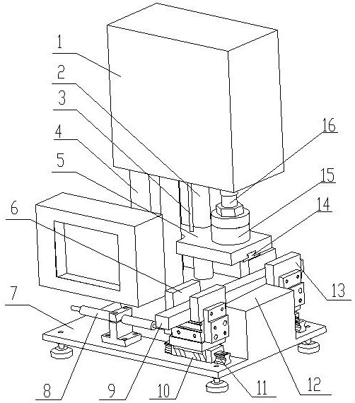
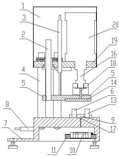
[0018] As shown in the figure, this embodiment includes a base 7 , and a workbench 12 is provided in the middle part of the front part of the upper surface of the base 7 . The bases 7 on both sides of the workbench are lower than the workbench 12, and the guide rails 11 arranged in the front and rear directions are respectively installed thereon, and the sliding seats 10 are respectively matched with the two guide rails 11, and the movable parts 9 are installed above each sliding seat 10. The splint 13 has a fixed splint 6 on the base 7 corresponding to the position of each movable splint 13 . On both sides of the rear of the base 7 there is a laterally moving cylinder 8, the piston rods of which are respectively connected with the sliding seat 10 on the same side to control the front and rear movement of the movable splint 13, so as to further enable the movable splint 13 to connect with the fixed splint on the same side 6 is fitted on both ends of the sample 9 to clamp the s...


PUM


Abstract

The invention relates to a compression ratio measuring device. The compression ratio measuring device comprises a base, wherein a workbench is arranged on the upper surface of the base, and a clampingmechanism, a pressurizing mechanism and a measuring mechanism corresponding to the workbench are further arranged on the base; the clamping mechanism comprises a transverse air cylinder arranged on the base, and a piston rod of the transverse air cylinder is fixedly connected with a sample piece movable clamping plate; the pressurizing mechanism comprises a pressurizing mechanism body and a pressing disc connected with the pressurizing mechanism body, and the pressurizing mechanism body is installed on the workbench through a stand column; and the measuring mechanism comprises a displacementsensor corresponding to a movable part of the pressurizing mechanism, a pressure sensor matched with the pressing plate and a temperature sensor capable of being matched with the sample piece. The compression ratio measuring device can provide a basis for increasing and decreasing cushion blocks of a coil in the production process of a transformer, the former height adjustment after coil forming is advanced to a winding process, the number of the cushion blocks is increased or decreased during winding, the coil is not damaged, a large amount of labor cost can be saved for each transformer, theproduction efficiency is improved, and the construction period is shortened.

Description

technical field [0001] The invention is a compression ratio measuring device. Background technique [0002] At present, in the manufacturing process of transformers, reactors, etc., it is a worldwide technical problem that the axial height is difficult to control due to changes in the compression ratio of laminates, coil pads, and wires. The actual compression is caused by differences in ambient temperature, humidity, and insulation manufacturers. The difference between the ratio and the theoretical data is the biggest problem that plagues us, which greatly affects product quality and production progress. To re-adjust the height of the coil, it is necessary to pry up the wire cake to increase or decrease the pads, which takes up a lot of man-hours, low labor efficiency, easy to damage the insulation, and brings new hidden dangers to the product quality. Contents of the invention [0003] The object of the present invention is to design a compression ratio measuring device...

Claims


Application Information

Patent Timeline
IPC IPC(8): G01N3/12G01N3/06
CPCG01N3/06G01N3/12G01N2203/0003G01N2203/0019G01N2203/0044
Inventor 谈翀燕飞东马玎韩志伟聂伟李发永胡鹏飞谢辉杨红燕王欢李东亮
Owner SHANDONG POWER EQUIP
Why Eureka
Try Eureka