
Radar wave stealth weapon equipment maintenance test method

A maintenance test and radar wave technology, which is applied in the field of radar wave stealth weapon equipment maintenance test, can solve the problems of high measurement environment requirements, high cost of outdoor field dynamic test tests, unsatisfactory and other problems, and achieve loose and improved site size and environmental requirements. The effect of maintaining test efficiency and reducing test cost

Active Publication Date: 2020-12-15
BEIJING CEWEI TECH
View PDF5 Cites 4 Cited by
  • Summary
  • Abstract
  • Description
  • Claims
  • Application Information

AI Technical Summary

Problems solved by technology

Among them, the compact field test environment has a small quiet area and limited target weight, which is suitable for scaled models and full-scale stealth weapon equipment component target testing; the outdoor static test field occupies a large area, is expensive, and is susceptible to interference, and is suitable for the design stage Full-scale stealth weapon equipment model test; outdoor field dynamic test test costs are high, the target attitude cannot be accurately controlled, and data repeatability is poor. It is suitable for real stealth weapon equipment testing in the production stage, and the defect location cannot be diagnosed; the construction cost of the near-field test site for the whole machine Expensive, few layouts, high requirements on the measurement environment, and low test efficiency
The above four measurement methods, in general, have high requirements for hardware, high requirements for the measurement environment, large construction investment, long cycle, and relatively fixed measurement sites, which cannot meet the needs of front-line users for daily stealth performance on-site maintenance of stealth weapons and equipment: Deployment Flexible and flexible, good environmental adaptability, convenient and fast maintenance and testing

Method used


Image

  • Radar wave stealth weapon equipment maintenance test method
  • Radar wave stealth weapon equipment maintenance test method
  • Radar wave stealth weapon equipment maintenance test method

Examples


Embodiment Construction

[0035] The present invention will be further described below in conjunction with drawings and embodiments. It should be understood that the specific embodiments described here are only used to explain the present invention, but not to limit the present invention. In addition, it should be noted that, for the convenience of description, only parts related to the present invention are shown in the drawings but not all content. Unless otherwise defined, all technical and scientific terms used herein have the same meaning as commonly understood by one of ordinary skill in the technical field of the invention. The terms used herein in the description of the present invention are for the purpose of describing specific embodiments only, and are not intended to limit the present invention. As used herein, the term "and / or" includes any and all combinations of one or more of the associated listed items.

[0036]The target to be measured in the embodiment of the present invention is r...


PUM


Abstract

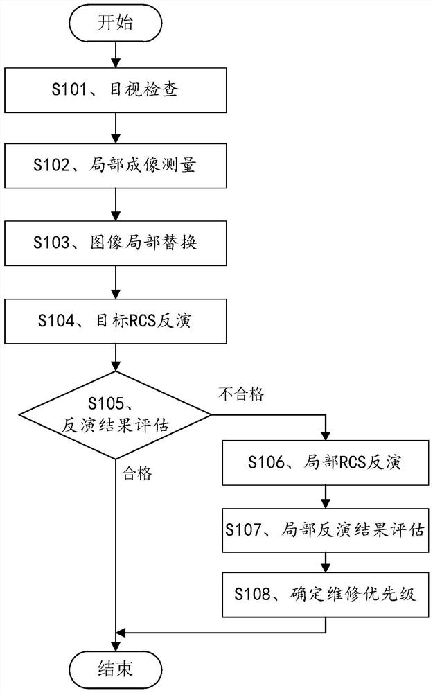
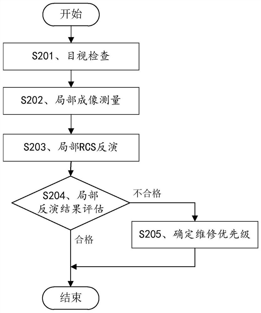
The invention provides a radar wave stealth weapon equipment maintenance test method, which comprises the steps of visually inspecting stealth defects possibly existing on the surface of a tested target, determining areas where the stealth defects are located, and numbering the areas; carrying out on-site near-field measurement on the area where the stealth defect of the measured target is located, and processing to obtain a far-field two-dimensional imaging result; replacing the corresponding area of the target overall image in the invisible weapon equipment overall two-dimensional image reference database with the obtained far-field two-dimensional imaging result to obtain a locally replaced measured target overall image, inverting the RCS to obtain a locally replaced measured target overall RCS, evaluating to determine whether to perform local RCS inversion or not, and if so, further evaluating the local RCS result to determine the maintenance priority. Through the method, possibleRCS defects of invisible weapons can be detected, identified and positioned, and the influence of local defects on the whole RCS is quantitatively evaluated, so that the maintenance test work is moretargeted and effective, the maintenance test cost is remarkably reduced, the detection period is shortened, and the maintenance test efficiency is improved.

Description

technical field [0001] The patent of the present invention relates to the technical field of RCS measurement of stealth weapons and equipment, and more specifically, relates to a method for maintaining and testing radar wave stealth weapons and equipment. Background technique [0002] In recent years, with the maturity of radar wave stealth technology and its wide application in military equipment, stealth weapons and equipment have been installed in troops one after another. [0003] During the use of stealth weaponry, the surface of stealth weaponry changes with use or natural wear and tear, such as materials on the weaponry, steps and gaps on the external structure of the weaponry, etc. A good state may change after a period of use, which will lead to the deterioration of the overall stealth performance of weapons and equipment. Therefore, in order to maintain or restore the stealth performance of stealth weapons and equipment, it is necessary to regularly perform mainte...

Claims


Application Information

Patent Timeline
Patent Type & Authority Applications(China)
IPC IPC(8): G01S13/88
CPCG01S13/88Y02A90/10
Inventor 张澎彭刚田进军
Owner BEIJING CEWEI TECH
Learn More