Disposable RFID electronic anti-counterfeit tag structure

An electronic anti-counterfeiting, one-time technology, which is applied in the direction of recording carriers, instruments, computer parts, etc. used by machines, can solve the problem that electronic tags do not have one-time use, and achieve the effect of improving security

Inactive Publication Date: 2020-12-15
广州维他科技有限公司
View PDF0 Cites 2 Cited by
  • Summary
  • Abstract
  • Description
  • Claims
  • Application Information

AI Technical Summary

Problems solved by technology

[0005] Aiming at the deficiencies of the prior art, the present invention provides a disposable RFID electronic anti-counterfeiting label structure, which has the advantages of one-time use of the electronic label and the ability to destroy the connection at the physical level, which improves the safety of product use and solves the problem of The vast majority of electronic tags do not have the function of one-time use, and a small number of one-time tags are also rewritten at the software level to achieve the purpose of one-time use, which is easier to be cracked

Method used


Image

  • Disposable RFID electronic anti-counterfeit tag structure
  • Disposable RFID electronic anti-counterfeit tag structure
  • Disposable RFID electronic anti-counterfeit tag structure

Examples


Embodiment 1

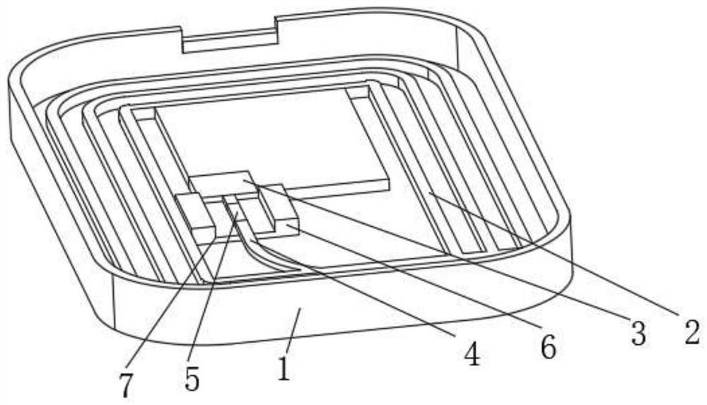
[0042] see Figure 1-5 , the present invention provides a technical solution: a disposable RFID electronic anti-counterfeiting label structure, including a base 1, the bottom of the inner wall of the base 1 is fixedly connected with the outer wall of the bottom plate 8, the top of the bottom plate 8 is connected with the bottom of the tag antenna 2 and The bottom of the tag chip 3 is fixedly connected, the tag chip 3 is located inside the tag antenna 2, the tag antenna 2 and the tag chip 3 are respectively fixedly connected to one end of two sets of copper wires 4, and the other ends of the two sets of copper wires 4 are respectively connected to the connecting wire 5 The two ends of the connecting wire 5 are welded, the bottom of the connection line 5 is in contact with the bottom inner wall of the groove 7, the groove 7 is opened on the top of the bearing seat 6, the bearing seat 6 is located inside the tag antenna 2, the bottom of the bearing seat 6 is in contact with the bo...

Embodiment 2

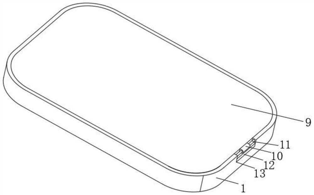
[0052] see figure 1 with Figure 6-7 , the present invention provides a technical solution: a disposable RFID electronic anti-counterfeiting label structure, including a base 1, the bottom of the inner wall of the base 1 is fixedly connected with the outer wall of the bottom plate 8, the top of the bottom plate 8 is connected with the bottom of the tag antenna 2 and The bottom of the tag chip 3 is fixedly connected, the tag chip 3 is located inside the tag antenna 2, the tag antenna 2 and the tag chip 3 are respectively fixedly connected to one end of two sets of copper wires 4, and the other ends of the two sets of copper wires 4 are respectively connected to the connecting wire 5 The two ends of the connecting wire 5 are welded, the bottom of the connection line 5 is in contact with the bottom inner wall of the groove 7, the groove 7 is opened on the top of the bearing seat 6, the bearing seat 6 is located inside the tag antenna 2, the bottom of the bearing seat 6 is in cont...


PUM


Abstract

The invention relates to the technical field of electronic tags, and discloses a disposable RFID electronic anti-counterfeit tag structure which comprises a base, the bottom of the inner wall of the base is fixedly connected with the outer side wall of a bottom plate, the top of the bottom plate is fixedly connected with the bottom of a tag antenna and the bottom of a tag chip, and the tag chip islocated on the inner side of the tag antenna. A tag antenna and the tag chip are fixedly connected with one ends of the two groups of copper wires respectively. According to the disposable RFID electronic anti-counterfeit tag structure, a white phosphorus sheet and a low-melting-point connecting wire are arranged, after shielding of the white phosphorus sheet is canceled, the white phosphorus sheet makes contact with air, the white phosphorus sheet generates an oxidation reaction, the white phosphorus sheet generates heat in the oxidation reaction process, and heat is transmitted to the connecting wire by a heating hole. Thus, the low-melting-point connecting line is fused, connection between the tag chip and the tag antenna is canceled, and the electronic tag cannot be scanned and used again.

Description

technical field [0001] The invention relates to the technical field of electronic labels, in particular to a disposable RFID electronic anti-counterfeit label structure. Background technique [0002] Electronic tags are also called radio frequency tags, transponders, and data carriers; readers are also called readout devices, scanners, reading heads, communicators, and readers (depending on whether the electronic tags can rewrite data wirelessly). The space (non-contact) coupling of radio frequency signals is realized through the coupling element between the electronic tag and the reader; in the coupling channel, energy transmission and data exchange are realized according to the timing relationship. Electronic tags have the following characteristics: Data storage: Compared with traditional tags, the capacity is larger (1bit-1024bit), data can be updated at any time, and can be read and written; Faster reading and writing speed, multi-target recognition and motion recogniti...

Claims


Application Information

Patent Timeline
Patent Type & Authority Applications(China)
IPC IPC(8): G06K19/077
CPCG06K19/07722G06K19/07798
Inventor 王美华
Owner 广州维他科技有限公司
Why Eureka
Try Eureka