Running wheel forging and pressing device of electric pole steel die

A pole steel mold and forging technology, applied in forging/pressing/hammer devices, driving devices of forging presses, swaging presses, etc., can solve the problem of high-temperature deformation of forging heads and molding dies, lower molding quality, and unfavorable service life and other issues, to achieve the effect of improving safety, increasing service life, and preventing damage due to excessive temperature

Pending Publication Date: 2020-12-18
JIANGSU HAI HENG BUILDING MATERIAL MACHINERY CO LTD
View PDF0 Cites 3 Cited by
  • Summary
  • Abstract
  • Description
  • Claims
  • Application Information

AI Technical Summary

Problems solved by technology

[0003] Hot forging refers to forging carried out above the metal recrystallization temperature, because increasing the temperature can improve the plasticity of the metal, but the existing hot forging device has the following disadvantages: 1. The forging head is in contact with the high-temperature blank for a long time during forging, which is easy to cause forging The high-temperature deformation of the head and the forming die not only reduces the forming quality, but also does not make use of the service life of the device; 2. After hot forging, there will be waste residue around and inside the die, which needs to be cleaned in time in the device, which is easy to be burned

Method used


Image

  • Running wheel forging and pressing device of electric pole steel die
  • Running wheel forging and pressing device of electric pole steel die
  • Running wheel forging and pressing device of electric pole steel die

Examples


Embodiment 1

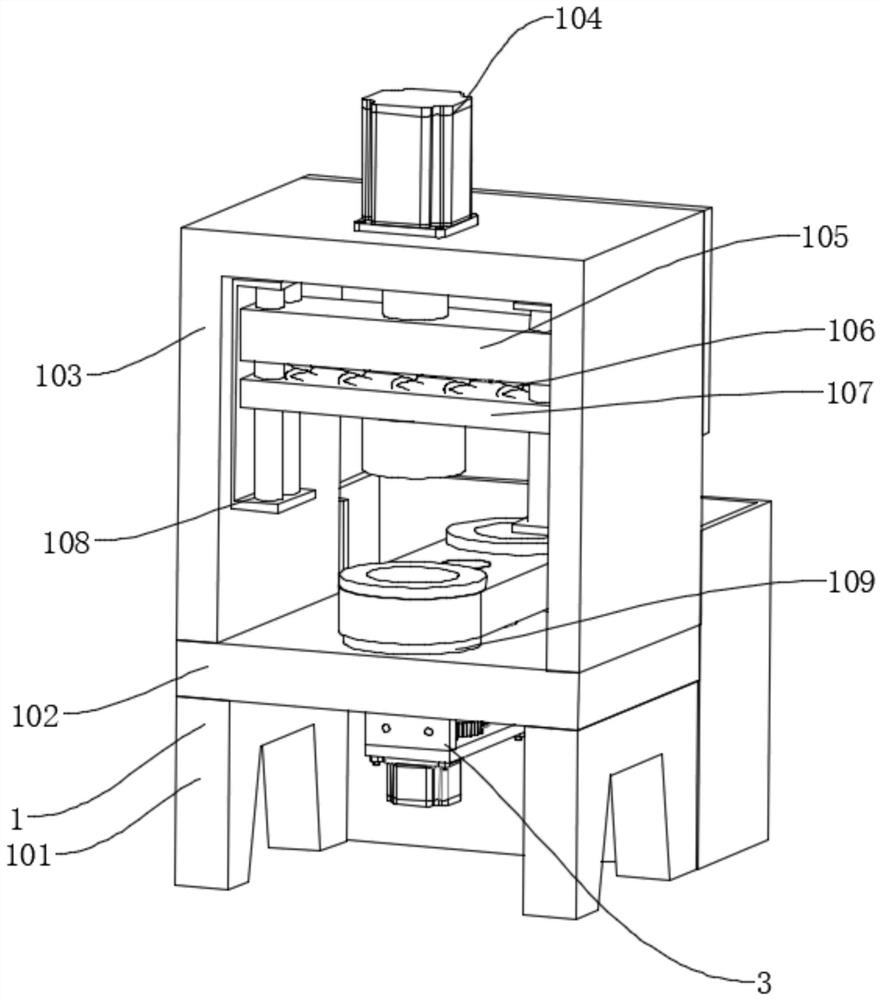
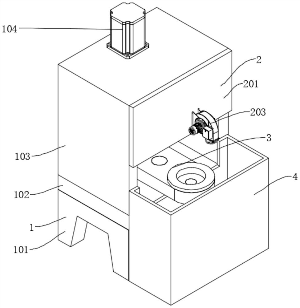
[0034] Such as Figure 1-7As shown, a running wheel forging device for a pole steel mold includes a forging mechanism 1 and a collection box 4. The forging mechanism 1 is mainly composed of a supporting leg 101, a supporting plate 102, a chassis 103, and a workbench 109. The top of the supporting leg 101 passes A support plate 102 is connected by bolts, and the top of the support plate 102 is connected with an organic case 103 and a workbench 109 by bolts. The workbench 109 is located inside the case 103, and the collection box 4 is located behind the support legs 101. It also includes a cooling mechanism 2 and a molding die 3. The mold 3 includes a rotating shaft 303, a rotating mounting plate 304, a first molding die body 305, and a second molding die body 306. The lower end of the rotating shaft 303 passes through the support plate 102 and extends to below the support plate 102, and is connected with a drive assembly. The shaft 303 is connected to the support plate 102 thro...

Embodiment 2

[0037] Such as Figure 8 As shown, the difference between Embodiment 2 and Embodiment 1 is that the drive assembly includes a drive motor 301 and a worm gear box 31, the drive motor 301 is connected to the bottom of the support plate 102 by bolts, and the output end of the drive motor 301 is connected to the worm gear box The worm of 31 is connected by a coupling, and the turbine of worm gear box 31 is connected to the lower end of rotating shaft 303 through a key, so that the worm gear and worm inside the worm gear box 31 can be driven to rotate by driving motor 301, and then the driving of rotating shaft 303 can be realized. Turn function.

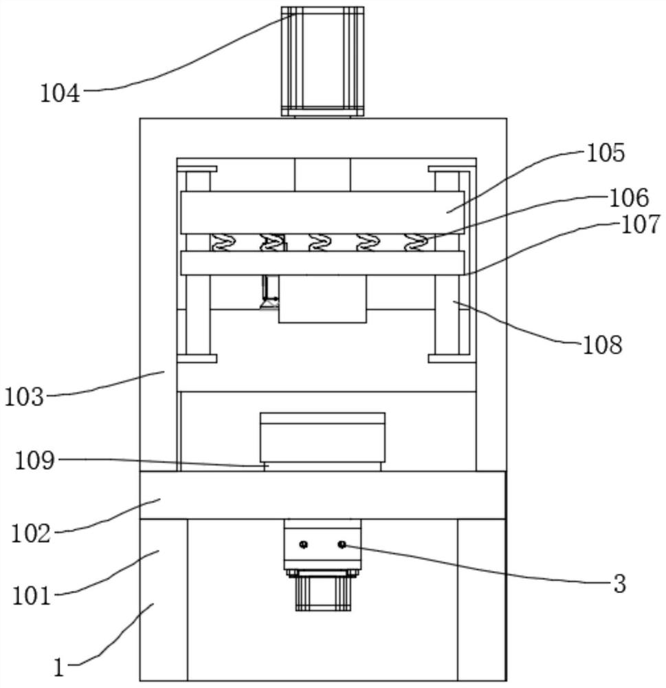
[0038] In the above structure, when in use, first start the external cooling fan 202 and the internal cooling fan 203, then put the material to be forged into the second molding die body 306, and then start the hydraulic cylinder 104, which drives the mounting plate 105 down, The mounting plate 105 squeezes the buffer spring 106, and th...


PUM


Abstract

The invention discloses a running wheel forging and pressing device of an of electric pole steel die. The running wheel forging and pressing device comprises a forging and pressing mechanism and a collecting box, the forging and pressing mechanism is mainly composed of supporting legs, a supporting plate, a machine box and a workbench, wherein the tops of the supporting legs are connected with thesupporting plate through bolts, the top of the supporting plate is connected with the machine box and the workbench through bolts, the workbench is located on the inner side of the machine box, the collecting box is located behind the supporting legs, and the device further comprises a cooling mechanism and a forming die. Due to the arrangement of the forming die, continuous work of the two forming die bodies is prevented, temperature rise of the two forming die bodies is slowed down, the function of cleaning impurities around the two forming die bodies on the outer side of the device is achieved, and safety is improved; and through the arrangement of the cooling mechanism, the function of rapidly cooling the two forming die bodies, buffer springs and a forging and pressing plate is achieved, and the service life of the device is prolonged.

Description

technical field [0001] The invention relates to the technical field of running wheel production of electric pole steel molds, in particular to a running wheel forging device for electric pole steel molds. Background technique [0002] The electric pole steel mold is a mold used to produce cement electric poles. The electric pole steel mold is placed on the running wheel, and then steel bars and mixed concrete are put in, the steel mold is covered and fixed by bolts, and the motor drives the running wheel to rotate. , and then the steel mold is rotated, and under the centrifugal force of the rotation, the hollow cement pole is formed and gradually solidified. In order to accelerate this solidification process, the water vapor burned by the boiler can be used to promote the denaturation of the cement structure after the rotation process. [0003] Hot forging refers to forging carried out above the metal recrystallization temperature, because increasing the temperature can impr...

Claims


Application Information

Patent Timeline
Patent Type & Authority Applications(China)
IPC IPC(8): B21J9/06B21J13/02B21K29/00B21J9/10B21J13/03F16F15/067
CPCB21J9/06B21J9/10B21J13/02B21J13/03B21K29/00F16F15/067
Inventor 田伟荣吴晓群凌俊
Owner JIANGSU HAI HENG BUILDING MATERIAL MACHINERY CO LTD
Why Eureka
Try Eureka