Tool for welding optical device flexible board and PCB

A technology of optical devices and soft boards, applied in welding equipment, auxiliary devices, manufacturing tools, etc., can solve problems such as unreliable fixing and clamping of devices, and achieve the effects of promoting rapid development, improving welding quality, and light weight

Active Publication Date: 2020-12-18
成都新易盛通信技术股份有限公司 +1
View PDF6 Cites 3 Cited by
  • Summary
  • Abstract
  • Description
  • Claims
  • Application Information

AI Technical Summary

Problems solved by technology

[0006] The object of the present invention is to provide a tooling for soldering optical device flexible boards and PCBs in view of the problem of unreliable device fixing and clamping in prior art for soldering optical device flexible boards and PCBs

Method used


Image

  • Tool for welding optical device flexible board and PCB
  • Tool for welding optical device flexible board and PCB
  • Tool for welding optical device flexible board and PCB

Examples


Embodiment 1

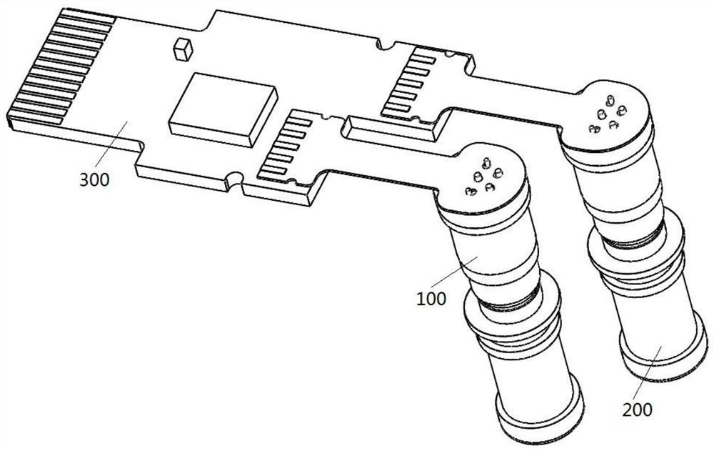
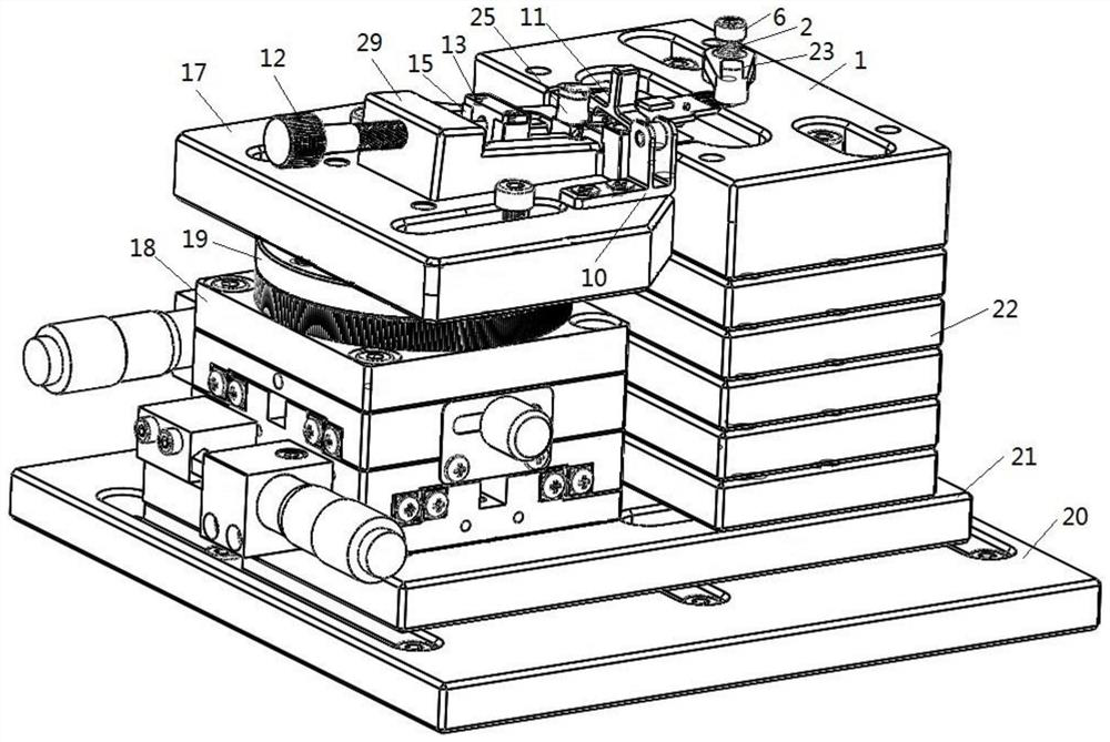
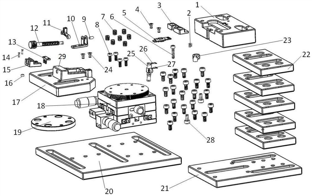
[0052] A welding tool for optical device flexible board and PCB, such as Figure 2-Figure 11 , including a bottom plate, a three-dimensional table 18, a spacer 22, a device-side card holder 17 and a PCB-side card holder 1. The welding tool is used to clamp the type A optical device 25 and weld the corresponding soft board of the optical device on the corresponding PCB5 board, wherein the soft board of the type A optical device includes the corresponding TOSA end soft board 26 and ROSA end soft board 27 .

[0053] Such as Figure 5-Figure 7 , the PCB end card holder 1 is mainly used to clamp the tail of the PCB5, and is used in conjunction with the device end card holder 17 relative to each other. After the PCB5 is installed, the optical device 25 on the PCB5 is suspended and does not interfere with the PCB socket 1. The shape, size and thickness of the PCB socket 1 are designed according to actual requirements. Specifically, such as Figure 6 , the PCB end card seat 1 is pr...

Embodiment 2

[0063] This embodiment provides a welding tool for the flexible board of the optical device and the PCB, such as Figure 12-Figure 16 , the tooling is used to horizontally clamp the B-type optical device 25 and weld the corresponding optical device soft board on the corresponding PCB5 board, wherein the B-type optical device soft board also includes the corresponding TOSA end soft board 26 and ROSA end soft board 27. When soldering B-type optical device flexible board does not need to be reshaped, its reshaped structure is as follows: Figure 14 , on the welding tooling structure and welding process, the main difference between this embodiment and embodiment 1 is:

[0064] The B-type optical device 25 is clamped in the device-side holder 17 in a horizontal clamping manner; correspondingly, in order to protect the flexible board, slotting is performed on the interference area of ​​the flexible board on the PCB-side holder 1 . Since the soft board of type B optical device does...

Embodiment 3

[0066] This embodiment provides a welding tool for the flexible board of the optical device and the PCB, such as Figure 17-Figure 22 , the tooling is used to longitudinally clamp the C-type optical device 25 and weld the corresponding optical device soft board on the corresponding PCB5 board, wherein the C-type optical device soft board also includes the corresponding TOSA end soft board 26 and ROSA end soft board 27. When soldering the C-type optical device soft board, its shaping structure is as follows: Figure 19 , on the welding tooling structure and welding process, the main difference between this embodiment and embodiment 1 is:

[0067] The C-type optical device 25 is clamped in the device end holder 17 in a longitudinal clamping manner; accordingly, the contact surface between the slider 15 and the device will be adjusted accordingly to meet the clamping and fixing requirements. The C-type device ROSA end soft board 27 of the tooling thermocompression welding is si...


PUM


Abstract

The invention relates to the field of communication modules, in particular to a tool for welding an optical device flexible board and a PCB. The tool comprises a bottom plate, a three-dimensional table, a cushion block, a device end clamping seat and a PCB end clamping seat. Only a small number of parts, such as the PCB end clamping seat, a PCB bonding pad end cushion block, the device end clamping seat, a sliding block and a deformation pressing device, need to be selectively replaced according to an actual product structure so that the tool can be suitable for most BIDI optical devices, canalso be used for positioning welding of single-transmitting and single-receiving optical devices, and is high in compatibility, universality and flexibility. The problems that in the welding process,the optical devices are loosened, a PCB is prone to tilting, and a BIDI optical device flexible board cannot be compatibly welded are effectively solved, and the tool is particularly suitable for welding of the optical device flexible board needing shaping.

Description

technical field [0001] The invention relates to the field of communication modules, in particular to a tooling used for welding an optical device soft board and a PCB. Background technique [0002] The rapid construction of global communication has greatly promoted the rapid development of the module communication industry, and good module performance has become the key to gain a foothold in this industry. Optical device flexible board refers to the type of flexible board corresponding to the packaged optical device in the module communication industry, in which the optical device and the flexible board are in a connected state. On the optical communication module, the optical communication device and the optical module PCB are connected through a flexible board (flexible printed circuit board FPC), and the FPC soft board is small in size, light in weight, and can be bent with a certain degree of freedom. The quality of the optical device flexible board and PCB welding has ...

Claims


Application Information

Patent Timeline
IPC IPC(8): B23K1/00B23K3/08
CPCB23K1/0008B23K3/08B23K3/087
Inventor 杨龙兵
Owner 成都新易盛通信技术股份有限公司
Why Eureka
Try Eureka