Flame tube head machining device and method

A flame tube head and processing method technology, applied in positioning devices, metal processing equipment, metal processing machinery parts, etc., can solve the problems of poor welding matching, welding deformation, difficulty in ensuring parts processing requirements and dimensional accuracy, and achieve cost Low cost, short processing cycle, and the effect of ensuring consistency and flatness

Active Publication Date: 2020-12-18
CHINA HANGFA GUIZHOU LIYANG AVIATION POWER CO LTD
View PDF8 Cites 2 Cited by
  • Summary
  • Abstract
  • Description
  • Claims
  • Application Information

AI Technical Summary

Problems solved by technology

However, during the welding process, the parts are prone to poor welding matching and welding deformation, so it is difficult to guarantee the final processing requirements and dimensional accuracy of the parts

Method used


Image

  • Flame tube head machining device and method
  • Flame tube head machining device and method
  • Flame tube head machining device and method

Examples


Embodiment Construction

[0036] The technical solutions of the present invention will be further described below in conjunction with the accompanying drawings and specific embodiments.

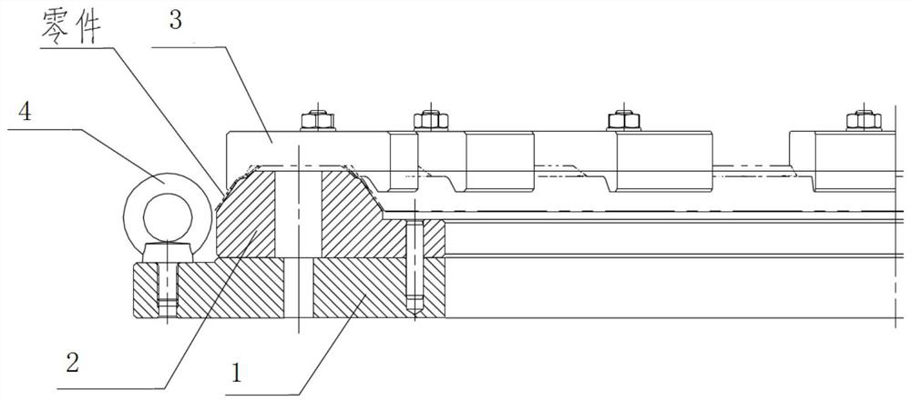
[0037] (1) Material preparation: Prepare the plate with the required thickness according to the requirements of the drawing. The thickness of the plate is consistent with the final material thickness of the part. The thickness of the wool when cutting the material must be the final part thickness, so as to ensure the final part thickness. The part is formed The material thickness reduction in the process meets the requirements, and there will be no excessive reduction in material thickness;

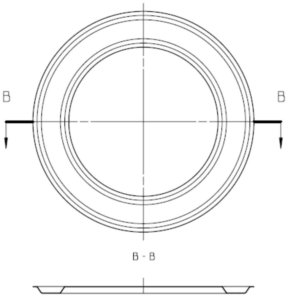
[0038] (2) Laser blanking: refer to the final shape of the part, and determine that the part wool is ring-shaped wool;

[0039] (3) Paint spraying: form a protective film on the surface of the parts to prevent direct contact between the parts and the mold, and play a protective and lubricating role;

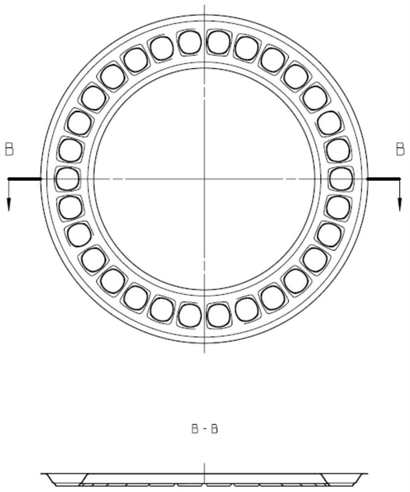
[0040] (4), the first moldi...


PUM


Abstract

The invention discloses a flame tube head machining device and method. An annular blank is adopted and placed in a forming die to form a U-shaped structure, then heat treatment is carried out, and flame tube convex hulls are formed through stretching. The machining device is adopted for clamping parts, end face turning machining is carried out, and the convex hulls are milled on the premise that aclamping device is not detached. When the convex hulls are milled, the convex hulls are pressed at intervals, the convex hulls which are not pressed are milled firstly, then the milled convex hulls are pressed, and therefore the remaining convex hulls are milled. The mode that the multiple convex hulls are milled at the same time is adopted during milling. The machining method is simple, the machining period is short, the machining cost is low, and the machining quality is good.

Description

technical field [0001] The invention belongs to the technical field of mechanical processing, and relates to a processing method and a processing device used for the head of a flame tube. Background technique [0002] The head of the aero-engine flame tube has a U-shaped ring in cross-section. The diameter of the part is greater than 700mm, the total height of the part is greater than 25mm, and there are more than 20 flanging holes (convex hulls) evenly distributed on the top of the part. Due to the large diameter of the part, And the surface structure is complex, and the parts are allowed to be welded with three welds. However, the parts are prone to poor welding matching and welding deformation during the welding process, and it is difficult to guarantee the final processing requirements and dimensional accuracy of the parts. Therefore, studying a reasonable and feasible process method and unique tooling is an inevitable choice for forming similar parts. Contents of the...

Claims


Application Information

Patent Timeline
IPC IPC(8): B23P15/00B23P23/06B23Q3/06
CPCB23P15/00B23P23/06B23Q3/06
Inventor 黄远东李明涂泉王维林员婷婷柳钰锴王春陈姣汤华
Owner CHINA HANGFA GUIZHOU LIYANG AVIATION POWER CO LTD
Why Eureka
Try Eureka