Lifting device for PC component production process and PC component production process

A technology of production process and lifting device, which is applied in the direction of supply device, unloading device, hoisting device, etc., can solve the problems of easy damage service life of the device, complicated production process operation, no compensation function, etc., to achieve convenient rotation, production The process steps are simple and the effect of increasing the scope of application

Pending Publication Date: 2020-12-18
江苏上建舜杰预制构件有限公司
View PDF7 Cites 2 Cited by
  • Summary
  • Abstract
  • Description
  • Claims
  • Application Information

AI Technical Summary

Problems solved by technology

[0003] However, in the prior art, the production process of most PC components is complicated to operate, and most of the lifting devices used for PC components do not have a buffer function, so that the stress borne during the lifting process is relatively large, resulting in easy damage to the device and a reduced service life, and most The lifting device used for PC components does not have a compensation function, and needs to accurately correspond to the position of the PC component to be demolded and lifted, resulting in a reduction in its scope of application

Method used


Image

  • Lifting device for PC component production process and PC component production process
  • Lifting device for PC component production process and PC component production process
  • Lifting device for PC component production process and PC component production process

Examples


Embodiment Construction

[0036] In order to make the technical problems, technical solutions and beneficial effects to be solved by the present invention clearer, the present invention will be further described in detail below in conjunction with the accompanying drawings and embodiments. It should be understood that the specific embodiments described here are only used to explain the present invention, not to limit the present invention.

[0037] It should be noted that when an element is referred to as being “fixed” or “disposed on” another element, it may be directly on the other element or be indirectly on the other element. When an element is referred to as being "connected to" another element, it can be directly connected to the other element or indirectly connected to the other element.

[0038]It is to be understood that the terms "upper", "lower", "front", "rear", "left", "right", "vertical", "horizontal", "top", "bottom", "inner" The orientation or positional relationship indicated by , "ou...


PUM


Abstract

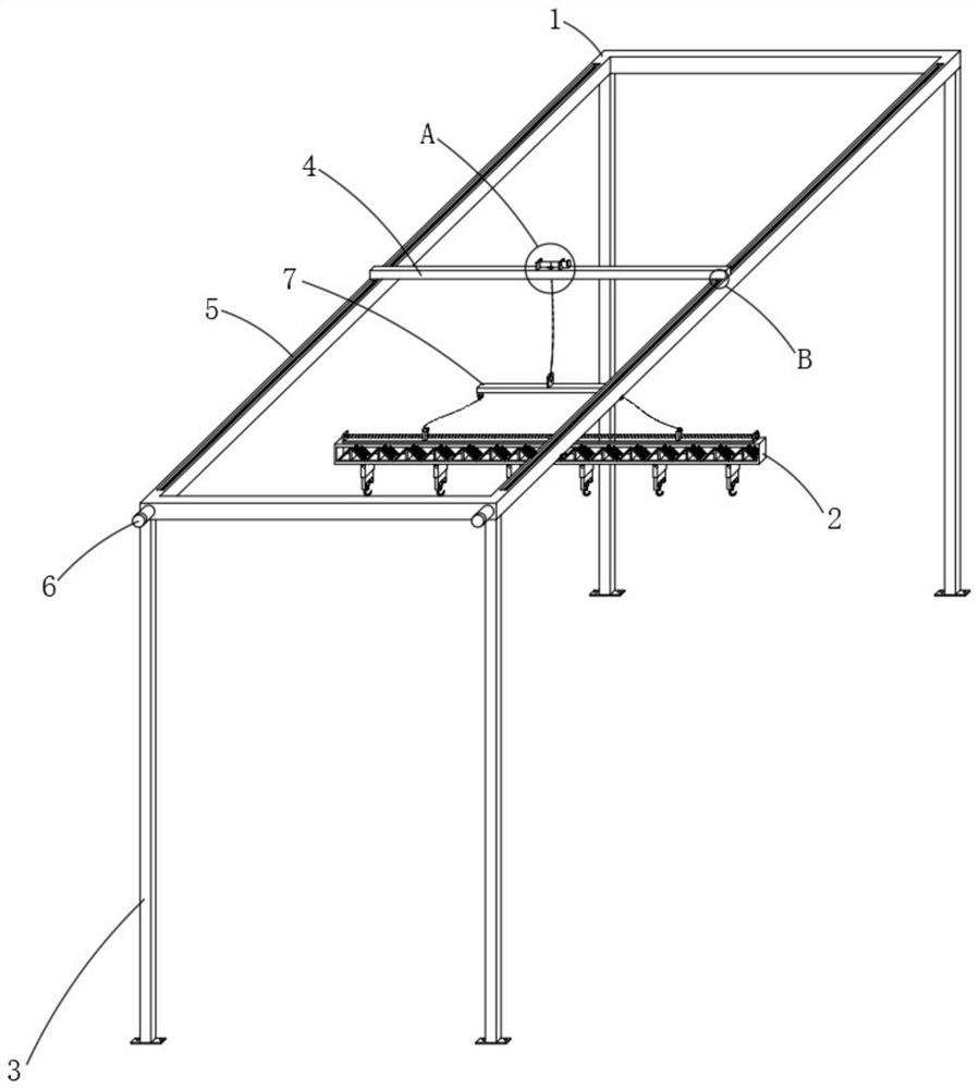
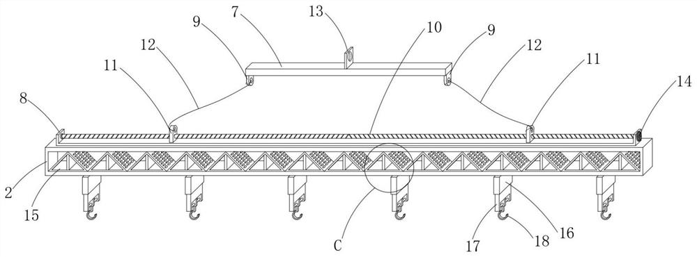
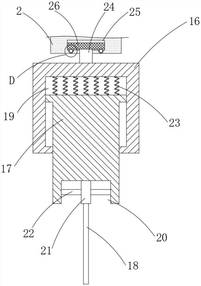
The invention discloses a lifting device for a PC component production process and the PC component production process, and relates to the technical field of PC component production and machining. Thelifting device comprises a main frame body, a bearing frame body, a cross rod and a bearing rod, and is characterized in that first connecting pieces are symmetrically and fixedly connected to the two sides of the bottom of the bearing rod, wherein a U-shaped piece is fixedly connected to the top of the bearing frame body, a transverse shaft is arranged inside the U-shaped piece, and second connecting pieces are symmetrically arranged on the two sides of the interior of the U-shaped piece. According to the lifting device, a vertical groove and a spring play a role in buffering a lifting hookin the vertical direction, so that the stress borne by the lifting hook in the lifting process is reduced, and the service life is prolonged; and a connecting shaft, a vertical block, a rotating shaft, a circular cavity, a rotating disc, a semicircular groove, a ball body and a bearing shaft are used in a matched mode, so that the lifting hook can be moved conveniently, the rotation of the liftinghook is facilitated, the compensation function is achieved, and the application range of the lifting device is enlarged.

Description

technical field [0001] The invention relates to the technical field of production and processing of PC components, in particular to a lifting device used in the production process of PC components and the production process of PC components. Background technique [0002] PC components are components used in construction, transportation, water conservancy and other fields. Compared with cast-in-place concrete, factory-produced concrete prefabricated parts have many advantages; safety: for construction workers, the relatively stable working environment in the factory Higher safety factor than complex site operations; Quality: The quality and process of building components can be better controlled through mechanized production; Speed: The standardization of prefabricated parts size and characteristics can significantly speed up installation speed and construction progress; Cost: and Compared with traditional on-site mold making, the molds in the factory can be reused and the ov...

Claims


Application Information

Patent Timeline
Patent Type & Authority Applications(China)
IPC IPC(8): B66C1/14B66C5/02B66C9/14B66C11/00B66C13/06B66C19/00B66D1/12F16F15/067B28B1/087B28B7/38B28B13/02B28B13/06
CPCB66C1/14B66C5/02B66C9/14B66C11/00B28B13/06B66C13/06B66C19/00B66D1/12F16F15/067B28B7/38B28B7/384B28B13/02B28B1/087
Inventor 刘俊强
Owner 江苏上建舜杰预制构件有限公司
Why Eureka
Try Eureka