Barrier gate for community security and protection
What is Al technical title?
Al technical title is built by PatSnap Al team. It summarizes the technical point description of the patent document.
A technology for community and barrier gates, which is applied in the direction of roads, roads, cooling/ventilation/heating renovation, etc. It can solve problems that affect the normal operation of equipment, reduce the practicability of barrier gates, and reduce the reliability of barrier gates, so as to improve the snow removal effect, Accelerated melting speed and improved environmental protection effect
Inactive Publication Date: 2020-12-18
张晓奎
View PDF5 Cites 0 Cited by
Summary
Abstract
Description
Claims
Application Information
AI Technical Summary
This helps you quickly interpret patents by identifying the three key elements:
Problems solved by technology
Method used
Benefits of technology
Problems solved by technology
[0003] Due to the lack of effective snow removal devices in the existing barrier gates, in snowy weather, the excessive snow accumulation on the barrier rods is avoided and the barrier rods are bent, which affects the normal operation of security work, thereby reducing the practicality of the existing barrier gates. Not only that, when the existing barrier gates are working, the electronic components inside the main body tend to generate more heat, resulting in too high internal temperature of the main body. If the heat is not dissipated in time, the electronic components will be damaged, thus affecting the performance of the equipment. work properly, thereby reducing the reliability of existing barrier gates
Method used
Image
Click on the blue label to locate the original text in one second.
Reading with bidirectional positioning of images and text.
Examples
Embodiment Construction
[0025] The present invention is described in further detail now in conjunction with accompanying drawing. These drawings are all simplified schematic diagrams, which only illustrate the basic structure of the present invention in a schematic manner, so they only show the configurations related to the present invention.
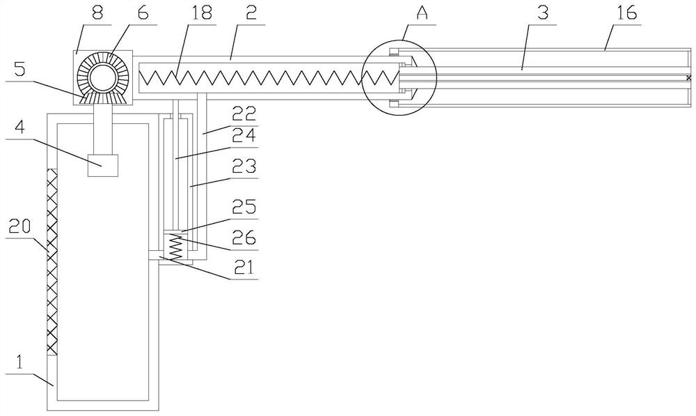
[0026] Such as figure 1 As shown, a barrier gate for community security includes a main body 1, a driving mechanism, a rotating shaft 7, a rotating block 8, a connection box 2, a stop rod 3 and two first bearings, and the driving mechanism is arranged on the main body 1. Inside, the first bearing is fixed above the main body 1, the two ends of the rotating shaft 7 are respectively fixedly connected to the inner rings of the two first bearings, the driving mechanism is connected to the rotating shaft 7, and the rotating block 8 is fixed on On the rotating shaft 7, one side of the connecting box 2 is fixedly connected with the rotating block 8, the other side o...
PUM
Abstract
The invention relates to a barrier gate for community security and protection. The barrier gate comprises a main body, a driving mechanism, a rotating shaft, a rotating block, a connecting box, a stoplever and two first bearings, and further comprises a snow removing mechanism and a heat dissipation mechanism. The snow removing mechanism comprises a first spring, a cleaning block, a moving block,a rotating assembly and two connecting rods. The rotating assembly comprises a first bearing, a connecting shaft, a rotating disc, a connecting wire and a transmission unit. The heat dissipation mechanism comprises a filter screen, an air cylinder, a piston, a first connecting pipe, a second connecting pipe, a second spring and a pull rope. According to the barrier gate for community security andprotection, through the snow removing mechanism, the snow removing function is achieved, and the connecting box and the stop lever are prevented from being bent due to excessive accumulated snow on the connecting box and the stop lever, so that normal operation of security and protection work is prevented from being affected, the reliability of the equipment is improved, the function of heat dissipation in the main body is achieved through the heat dissipation mechanism, normal operation of the equipment is prevented from being affected by overheating in the main body, and the reliability ofthe equipment is improved.
Description
technical field [0001] The invention relates to the field of intelligent security, in particular to a barrier gate for community security. Background technique [0002] Barrier gates, also known as car stoppers, are passage entrance and exit management equipment specially used to restrict motor vehicles on the road. They are now widely used in highway toll stations and parking lot systems to manage vehicle passages and to manage vehicle entry and exit. [0003] Due to the lack of effective snow removal devices in the existing barrier gates, in snowy weather, the excessive snow accumulation on the barrier rods is prevented from bending the barrier rods, which affects the normal operation of security work, thereby reducing the practicality of the existing barrier gates. Not only that, when the existing barrier gates are working, the electronic components inside the main body tend to generate more heat, which will cause the internal temperature of the main body to be too high. ...
Claims
Application Information
Patent Timeline
Application Date:The date an application was filed.
Publication Date:The date a patent or application was officially published.
First Publication Date:The earliest publication date of a patent with the same application number.
Issue Date:Publication date of the patent grant document.
PCT Entry Date:The Entry date of PCT National Phase.
Estimated Expiry Date:The statutory expiry date of a patent right according to the Patent Law, and it is the longest term of protection that the patent right can achieve without the termination of the patent right due to other reasons(Term extension factor has been taken into account ).
Invalid Date:Actual expiry date is based on effective date or publication date of legal transaction data of invalid patent.