
Energy-saving radiator for space optical remote sensor CCD component

A space optical remote sensing and heat dissipation device technology, applied in the direction of measuring instrument components, measuring devices, instruments, etc., can solve the problems of unable to guarantee the normal start-up temperature, high power consumption of CCD components, excessive compensation heating power consumption, etc., and achieve compact structure , Simple processing and assembly, good heat dissipation effect

Active Publication Date: 2014-08-06
CHANGCHUN INST OF OPTICS FINE MECHANICS & PHYSICS CHINESE ACAD OF SCI
View PDF4 Cites 5 Cited by
  • Summary
  • Abstract
  • Description
  • Claims
  • Application Information

AI Technical Summary

Problems solved by technology

Due to the strong heat conduction ability of the heat pipe, this thermal control measure can effectively dissipate the heat of the CCD components, but it will also bring about the problem of temperature compensation, that is, when the space optical remote sensor is in a non-working period, due to heat dissipation With the existence of the channel, the CCD component will be in a low temperature state under the action of the lower temperature external radiator
Although the low temperature state can reduce the thermal noise and dark current in the electronic signal, the CCD device not only cannot guarantee its normal start-up temperature in the low temperature state, but also black spots will appear, which will affect the image quality.
The current solution is usually to perform compensation heating to maintain the temperature of the CCD component, but its biggest disadvantage is that the power consumption of the CCD component is usually very large, so the required compensation heating power consumption is also very large, which not only causes a waste of energy, especially For spacecraft with frequent maneuvers, drastic changes in the external environment, and energy shortages, excessive compensation for heating power consumption is even impossible

Method used


Image

  • Energy-saving radiator for space optical remote sensor CCD component
  • Energy-saving radiator for space optical remote sensor CCD component
  • Energy-saving radiator for space optical remote sensor CCD component

Examples


Embodiment Construction

[0021] Combine below Figure 1-3 Specific embodiments of the present invention will be described in detail.

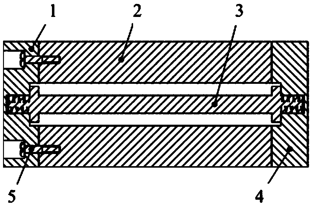
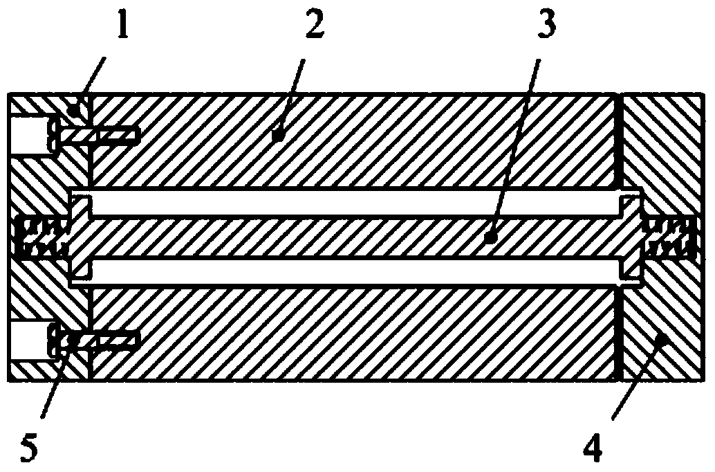
[0022] The energy-saving heat dissipation device for the space optical remote sensor CCD assembly of the present invention includes: a hot end 1 , a heat conduction section 2 , a positioning rod 3 , a cold end 4 , and a connecting screw 5 .

[0023] The hot end 1 and the heat conduction section 2 are connected by four titanium alloy connecting screws 5; the positioning rod 3 is directly connected with the hot end 1 and the cold end 4 through threads; It has the functions of positioning, pointing and supporting.

[0024] In addition, the gap between the heat conduction section 2 and the cold end 4 in the energy-saving heat dissipation device of the present invention is determined according to different heat dissipation requirements (such as CCD component power consumption, temperature requirements) and the difference in selected materials. The gap is arranged as follow...


PUM


Abstract

The invention relates to the field of space photoelectricity measurement and control, in particular to an energy-saving radiator for a space optical remote sensor CCD component. The device comprises a hot end, a heat conduction segment, a positioning rod and a cold end. The heat conduction segment is arranged between the hot end and the cold end, the hot end is fixedly connected with the heat conduction segment, the positioning rod is arranged inside the heat conduction segment, the two ends of the positioning rod are connected with the hot end and the cold end in a threaded mode respectively, the heat conduction segment and the cold end are arranged at intervals, the hot end and the cold end are made of high thermal conductivity materials respectively, the heat conduction segment is made of materials with high thermal conductivity and a high linear expansion coefficient, the positioning rod is made of materials with low thermal conductivity and a low linear expansion coefficient, and the linear expansion coefficient of the materials of the heat conduction segment is greater than that of the positioning rod. The energy-saving radiator has the advantages of being compact in structure, simple in assembly, strong in heat conduction capacity, good in energy-saving effect and low in cost.

Description

technical field [0001] The invention belongs to the field of space photoelectric measurement and control, and in particular relates to an energy-saving heat dissipation device for a CCD component of a space optical remote sensor. Background technique [0002] The CCD component is the core component of the space optical remote sensor. Its good working condition is the key to ensure the imaging quality. The CCD component has very strict requirements on its own working temperature. Too high or too low temperature will reduce its photoelectric conversion ability. Due to the special working requirements of space optical remote sensors, CCD components have the characteristics of small size, high heat generation, and intermittent work. The compensatory heating to prevent its temperature from being too low poses a special problem in the thermal control of CCD components, namely the conflicting requirements of heat dissipation and temperature compensation. [0003] When the space op...

Claims


Application Information

Patent Timeline
IPC IPC(8): G01D11/00
Inventor 郭亮张旭升毛阿龙黄勇胡日查
Owner CHANGCHUN INST OF OPTICS FINE MECHANICS & PHYSICS CHINESE ACAD OF SCI
Learn More