

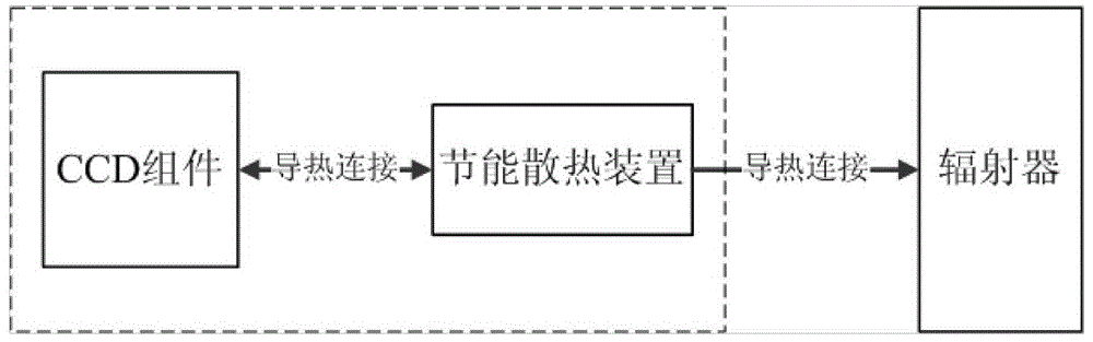
An energy-saving cooling device for space optical remote sensor CCD components
A space optical remote sensing and heat dissipation device technology, applied in the direction of measuring instrument components, measuring devices, instruments, etc., can solve the problems of unable to guarantee normal starting temperature, excessive compensation heating power consumption, large power consumption of CCD components, etc., and achieve compact structure , Good cooling effect, simple processing and assembly
- Summary
- Abstract
- Description
- Claims
- Application Information
AI Technical Summary
Problems solved by technology
Method used
Image


Examples
Embodiment Construction
[0021] Combine below Figure 1-3 Specific embodiments of the present invention will be described in detail.
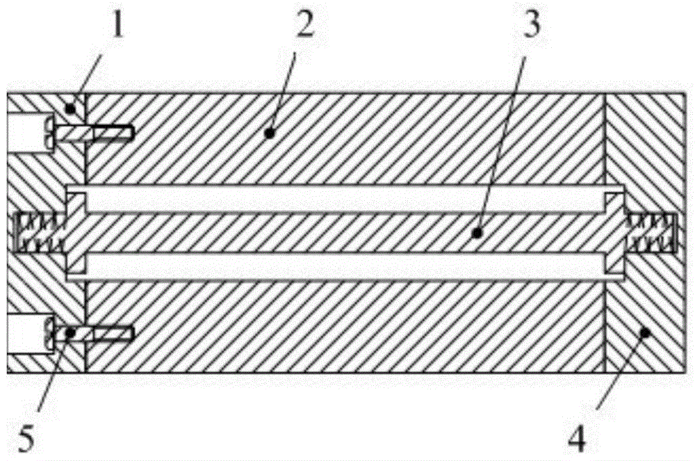
[0022] The energy-saving heat dissipation device for the space optical remote sensor CCD assembly of the present invention includes: a hot end 1 , a heat conduction section 2 , a positioning rod 3 , a cold end 4 , and a connecting screw 5 .
[0023] The hot end 1 and the heat conduction section 2 are connected by four titanium alloy connecting screws 5; the positioning rod 3 is directly connected with the hot end 1 and the cold end 4 through threads; It has the functions of positioning, pointing and supporting.
[0024] In addition, the gap between the heat conduction section 2 and the cold end 4 in the energy-saving heat dissipation device of the present invention is determined according to different heat dissipation requirements (such as CCD component power consumption, temperature requirements) and the difference in selected materials. The gap is arranged as follow...
PUM
 Abstract
Description
Claims
Application Information