Contact clamping force test auxiliary device for fuse type isolation switch

A technology of isolating switches and auxiliary devices, which is applied in the direction of measuring devices, instruments, force/torque/power measuring instruments, etc., can solve problems such as difficult centering, and achieve the effect of ensuring stability

Active Publication Date: 2020-12-18
STATE GRID CORP OF CHINA +2
View PDF11 Cites 0 Cited by
  • Summary
  • Abstract
  • Description
  • Claims
  • Application Information

AI Technical Summary

Problems solved by technology

[0005] The purpose of the present invention is to provide a contact clamping force test auxiliary device for a fuse-type isolating switch, to solve the technical problem in the prior art that the drag hook of the tension meter is not easy to be centered when hooking the hand-held section of the handle

Method used


Image

  • Contact clamping force test auxiliary device for fuse type isolation switch
  • Contact clamping force test auxiliary device for fuse type isolation switch
  • Contact clamping force test auxiliary device for fuse type isolation switch

Examples


Embodiment 1

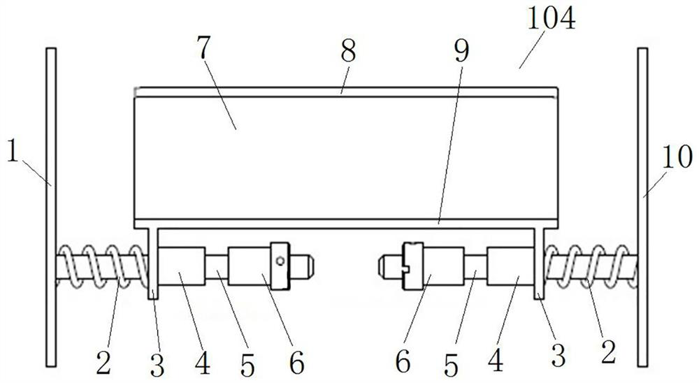
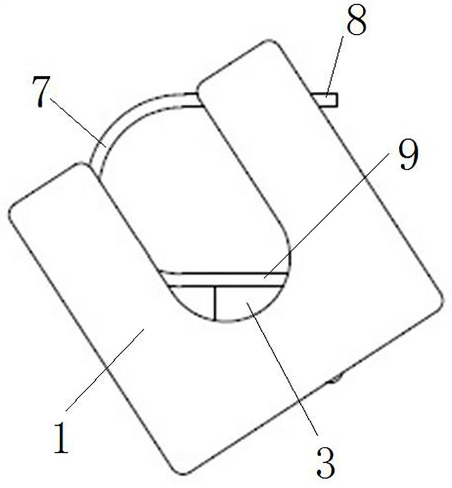
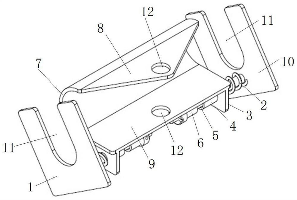
[0040] Such as figure 1 with figure 2 As shown, the contact clamping force test auxiliary device 104 includes a left top pressure plate 1 and a right top pressure plate 10, the left top pressure plate 1 and the right top pressure plate 10 are arranged in parallel and spaced apart, the right side of the left top pressure plate 1 and the left side of the right top pressure plate 10 Both sides are provided with support shafts 5, that is, two support shafts 5 are arranged on opposite sides of the two top pressure plates, and the support shafts 5 are arranged perpendicular to the respective top pressure plates, wherein the two support shafts 5 are coaxial and arranged at intervals. Wherein, the opposite sides of the two pressing plates are used to press fit with the inner side of the bending section of the handle on the cover plate.

[0041] In this embodiment, a pulling plate is provided between the left top pressure plate 1 and the right top pressure plate 10. The pulling plate...

Embodiment 2

[0051] In Embodiment 1, only one compression spring is provided between the ear plate 3 and the corresponding top pressure plate, and the specifications of the two compression springs 2 are the same, so that the pulling plate is in the two top positions under the elastic force of the two compression springs 2. The middle position of the pressure plate, in this embodiment, a compression spring is set between the ear plate and the left top pressure plate, and two compression springs are set between the ear plate and the right top pressure plate, wherein, the two pressure springs between the ear plate and the right top pressure plate The elastic active force of stage clip and the elastic active force of a stage clip between lug plate and left top pressure plate, make pulling plate be in the middle position of two top pressure plates under the elastic active force of three stage clips.

Embodiment 3

[0053] In Embodiment 1, the plate body is a U-shaped structure, including two parallel plate sections and a connecting plate section 7, the two parallel plate sections are provided with hook holes, and the connecting plate section 7 is used to push and cooperate with the hand-held section of the handle 103 , to drive the handle 103 to move together when the dynamometer pulls the pulling plate, wherein the connecting plate section 7 constitutes the pushing part of the handle; in this embodiment, the plate body is an L-shaped structure, including a vertical plate section and a horizontal plate section, The horizontal plate section is provided with a hook hole, and the vertical plate section is used to stop and cooperate with the handle, so as to drive the handle to move together when the tension gauge pulls the pulling plate, wherein the vertical plate section constitutes the pushing part of the handle.


PUM


Abstract

The invention relates to a contact clamping force test auxiliary device for a fuse type isolation switch. The contact clamping force test auxiliary device for a fuse type disconnecting switch comprises two top pressing plates and a traction plate. The two top pressing plates are arranged in parallel at an interval, and the opposite sides of the two top pressing plates are matched with the inner side of a bent section of a handle on a cover plate in a top pressing mode; the traction plate is arranged between the two top pressing plates, a hook hole and a handle pushing part are arranged on thetraction plate, a hook of the tension meter is hooked in the hook hole, and the handle pushing part is matched with the handheld section of the handle in a pushing mode so as to drive the handle to move together when the tension meter pulls the traction plate; compression type elastic pieces are arranged between the traction plate and the two top pressing plates, the compression type elastic pieces apply elastic acting forces away from each other to the traction plate and the corresponding top pressing plates, and the elastic acting forces borne by the two top pressing plates are the same, sothat the traction plate is located between the two top pressing plates. The problem that a drag hook of a tension meter in the prior art is not easy to be centered when hooking a handheld section of ahandle is solved.

Description

technical field [0001] The invention relates to a contact clamping force test auxiliary device for a fuse type isolating switch. Background technique [0002] For the fuse-type isolating switch, the internal resistance of the fuse core cannot be greatly reduced because the fuse core is required to heat and fuse rapidly when passing a fault current such as a short circuit, so as to disconnect the circuit and ensure the safety of other equipment. In order to reduce the temperature rise of the fuse-type isolating switch, generally by increasing the size of its incoming and outgoing copper bars, adding ventilation and cooling holes on its shell, increasing the contact area between the fuse core and the contact, and increasing the clamping force of the contact. The above method of increasing the clamping force of the contact can reduce the contact resistance between the contact and the fuse core, thereby reducing the heat generation. The contact clamping force test can reflect t...

Claims


Application Information

Patent Timeline
Patent Type & Authority Applications(China)
IPC IPC(8): G01L5/00
CPCG01L5/00
Inventor 韩增新彭云李科帅李新新苏文玉谷许磊王湘涛黄文静雷磊张丽娜温培科常琨璘周非非王豪东张号徐健男余顺行马晨晨
Owner STATE GRID CORP OF CHINA
Why Eureka
Try Eureka