Multi-degree-of-freedom wire harness fatigue test equipment and fatigue test method thereof

A fatigue test and degree-of-freedom technology, applied in the application field, can solve problems such as unsuitable multi-direction compliance motion, unsuitable product life verification, design redundancy, etc., to accelerate the exposure of fatigue hazards, reduce workload, Time saving effect

Pending Publication Date: 2020-12-18
ZHEJIANG YONGGUI ELECTRIC EQUIP
View PDF0 Cites 0 Cited by
  • Summary
  • Abstract
  • Description
  • Claims
  • Application Information

AI Technical Summary

Problems solved by technology

[0002] The current dynamic wire harness applicability and life simulation analysis and verification methods mainly include the following two methods: 1. Theoretical calculation and simulation, using design software or simulation software for measurement and simulation analysis of motion parameters; 2. Multiple single-degree-of-freedom simulations Continuous accumulative test verification, through the combination of certain tooling and structure, physical simulation analysis is carried out according to the motion parameters; the first one above is to calculate and simulate based on theoretical data, the applicability is different from the actual situation, and the simulation analysis of life requires a lot of foundation Data accumulation can be used

Method used


Image

  • Multi-degree-of-freedom wire harness fatigue test equipment and fatigue test method thereof
  • Multi-degree-of-freedom wire harness fatigue test equipment and fatigue test method thereof

Examples


Embodiment Construction

[0029] The present invention will be further described below in conjunction with drawings and embodiments.

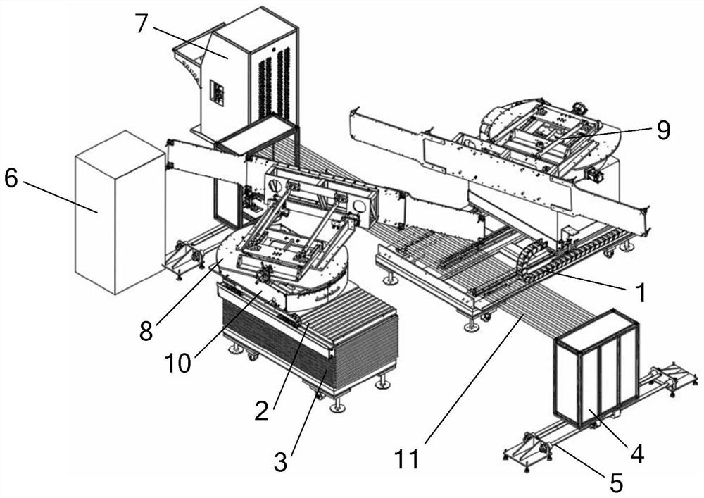
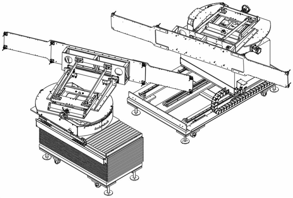
[0030] Such as figure 1 with 2As shown, the multi-degree-of-freedom wire harness fatigue test equipment includes a longitudinal movement mechanism 1, a transverse movement mechanism 2, a vertical movement mechanism 3, an angle adjustment component, a cable height detection mechanism 4, a longitudinal guide rail 5, a vertical movement linear module and a test piece Mounting plate; the cable height detection mechanism 4 is arranged between the vertical movement mechanism 1 and the lateral movement mechanism 2, including an infrared transmitter and an infrared receiver; the infrared receiver receives the light 11 emitted by the infrared transmitter; the infrared transmitter and the infrared receiver The devices are respectively driven by a vertical linear module to move up and down, and the support bases of the two vertical linear modules and the two longitudinal guide ra...


PUM


Abstract

The invention discloses multi-degree-of-freedom wire harness fatigue test equipment and a fatigue test method thereof. Existing dynamic wire harness applicability and service life simulation analysisthat multiple single-degree-of-freedom are simulated and then accumulated, and a test result is greatly different from a multi-degree-of-freedom automatic combination condition. A cable height detection mechanism comprises an infrared emitter and an infrared receiver, the infrared emitter and the infrared receiver are respectively driven by a vertical moving linear module to move up and down, andsupporting seats of the two vertical moving linear modules and two longitudinal guide rails respectively form sliding pairs; the transverse moving mechanism is driven by the vertical moving mechanismto move up and down; the longitudinal moving mechanism and the transverse moving mechanism are each provided with an angle adjusting assembly. In each angle adjusting assembly, a deflection mechanismis arranged at the top of a side rolling mechanism, and a nodding mechanism is arranged at the top of the deflection mechanism; a test piece mounting plate is arranged on the nodding mechanism of eachangle adjusting assembly, and a plurality of anti-collision sensing devices are arranged on the test piece mounting plates. Whether the length of the wire harness meets the actual use requirement ornot can be verified, and a fatigue test is conducted.

Description

technical field [0001] The invention belongs to the application fields of industry, rail transit and new energy, and specifically relates to a multi-degree-of-freedom wire harness fatigue test device and a fatigue test method thereof. Background technique [0002] The current dynamic wire harness applicability and life simulation analysis and verification methods mainly include the following two methods: 1. Theoretical calculation and simulation, using design software or simulation software for measurement and simulation analysis of motion parameters; 2. Multiple single-degree-of-freedom simulations Continuous accumulative test verification, through the combination of certain tooling and structure, physical simulation analysis is carried out according to the motion parameters; the first one above is to calculate and simulate based on theoretical data, the applicability is different from the actual situation, and the simulation analysis of life requires a lot of foundation Da...

Claims


Application Information

Patent Timeline
IPC IPC(8): G01N3/38G01N3/02G01N3/06
CPCG01N3/38G01N3/02G01N3/06G01N3/068G01N2203/0005G01N2203/005G01N2203/0073G01N2203/0641Y02E30/30
Inventor 周青王海波吕浪平许委阳叶鸣华
Owner ZHEJIANG YONGGUI ELECTRIC EQUIP
Why Eureka
Try Eureka