
Intelligent wall switch

a wall switch and intelligent technology, applied in the direction of switches, relays, contact mechanisms, etc., can solve the problems of limiting the application of wall switches in as many households as expected, and indicating that leds are not bright enough for users to clearly distinguish, so as to achieve the effect of allowing users to touch the wall switch in a large sensor area

Inactive Publication Date: 2011-11-08
LIU YUAN SHENG +1
View PDF3 Cites 32 Cited by
  • Summary
  • Abstract
  • Description
  • Claims
  • Application Information

AI Technical Summary

Benefits of technology

"The present invention is an intelligent wall switch that has the following technical effects:\n1. It provides larger sensor areas for easy touch.\n2. It emits lights clearly to indicate its location.\n3. It can remember various types of infrared codes to work with different remote controllers.\n4. It includes an extended operation panel with a sensor area and a glass panel with a conducting film.\n5. It has a flexible cable connected to a second conducting film on the glass.\n6. It has a controller system with a power module, relays, and infrared receiver.\n7. It has a connecting piece and housing for the power module.\nOverall, the intelligent wall switch provides improved user experience and convenience for controlling the wall switch."

Problems solved by technology

Due to the area of the extended operation panel is not large enough for the elder to easily touch the panel precisely, and the conventional wall switch can only match with a selected infrared remote controller, so will these disadvantages limit the application of the wall switches in as many households as expected to be.
Furthermore, the indicating LEDs are not bright enough for users to clearly distinguish the working status of the wall switches.

Method used


Image

  • Intelligent wall switch
  • Intelligent wall switch
  • Intelligent wall switch

Examples


Embodiment Construction

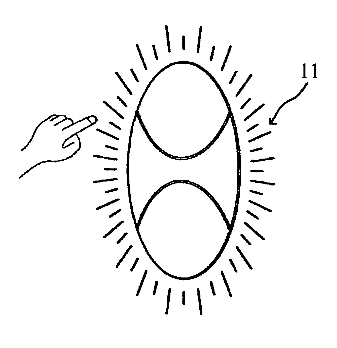
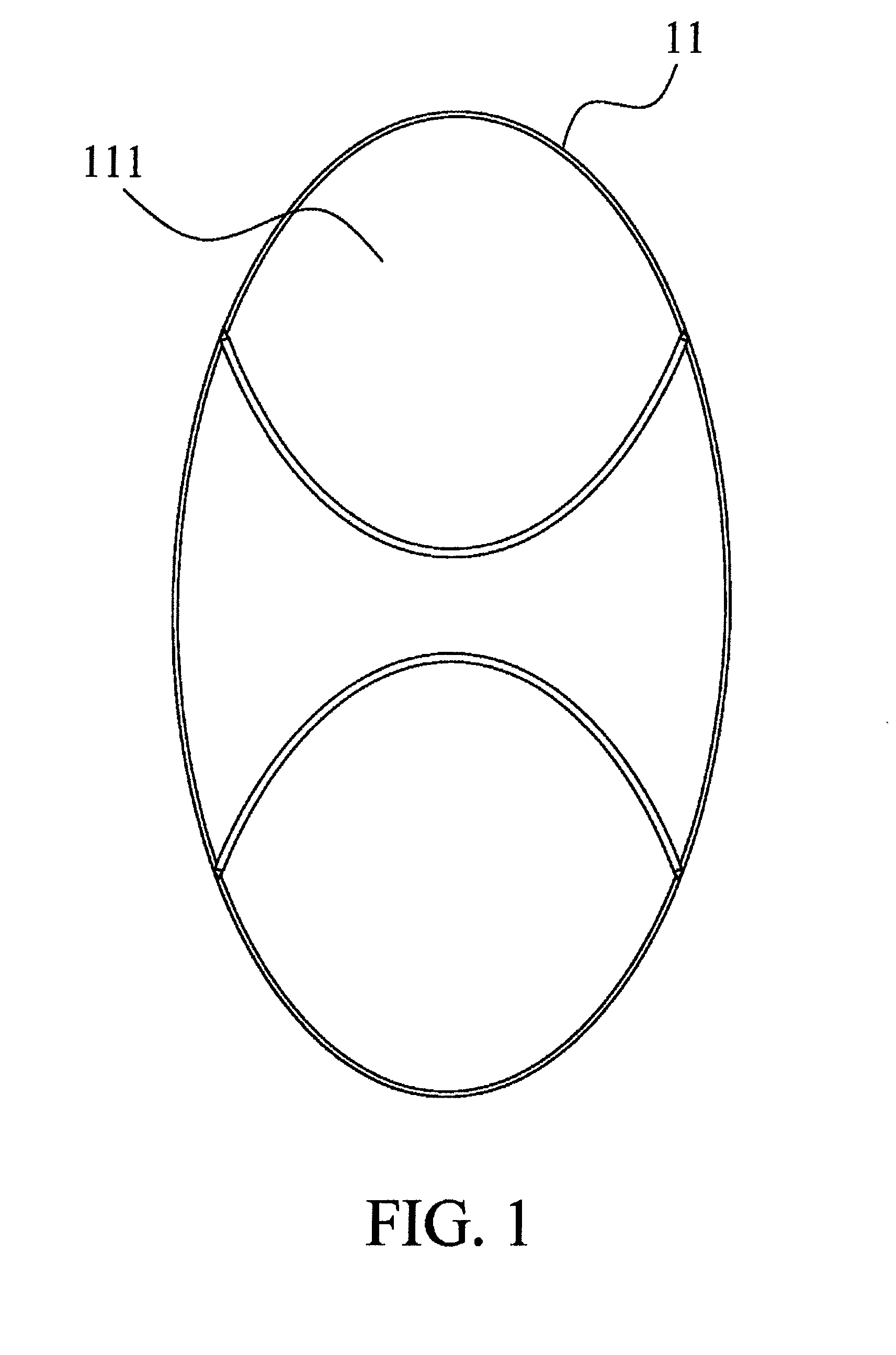
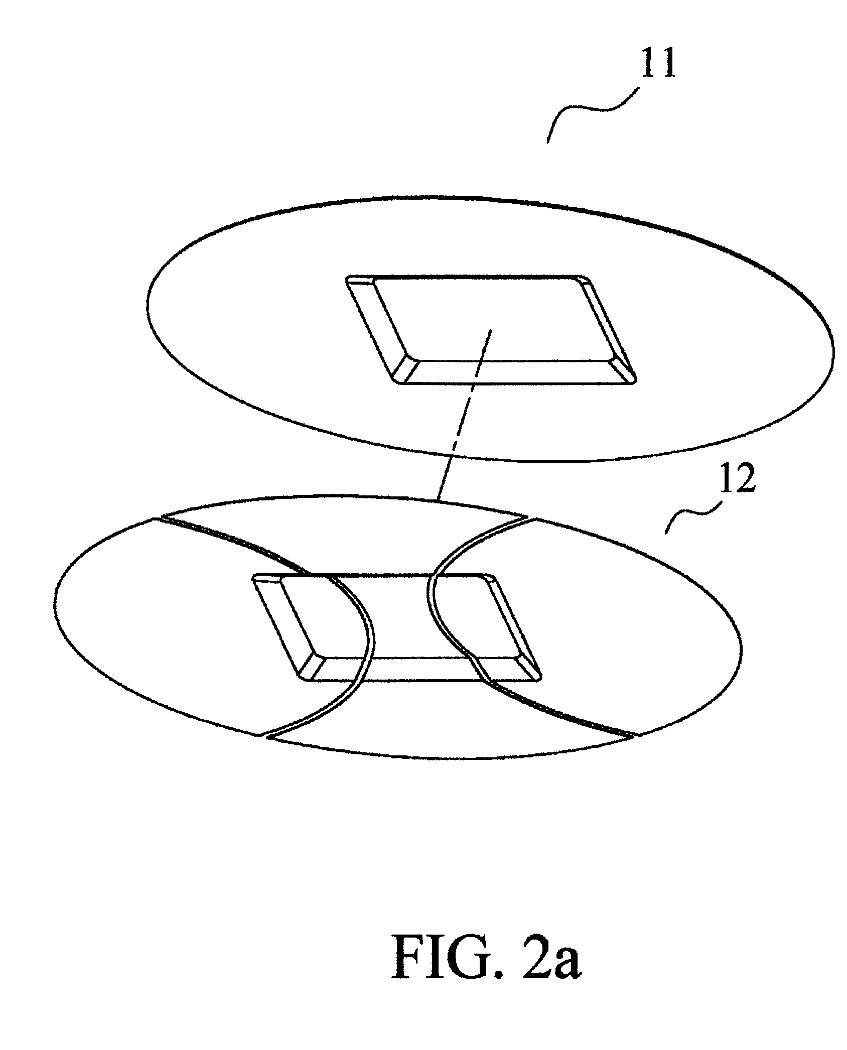
[0030]Referring to FIGS. 1-6, an intelligent wall switch in accordance with the present invention comprises an extended operation panel 11 made of transparent plastic materials and including a plurality of sensor areas 111, each sensor area 111 including a first conducting film 12 and a glass 13 disposed on the back side thereof respectively, a plurality of second conducting films 14 being made of transparent indium oxide materials and plated onto the back side of the glass 13 for corresponding to the sensor areas 111 of the extended operation panel 11, the glass 13 serving as a substrate and further including a name plate 15 attached on the back side thereof, and the extended operation panel 11, the glass 13, and the name plate 15 being combined together. The second conducting films 14 are connected to a flexible cable 16 on which a first circuit board 17 is welded and includes at least one backlight LED 171 and an infrared emitter 172, a plastic frame 18 is disposed on a back side...


PUM


Abstract

An intelligent wall switch comprises an extend operation panel including sensor areas with a first conducting film; a glass on the back sides of the sensor areas including second conducting films; a first circuit board including a backlight LED and an infrared emitter and connected to a flexible cable connected to the second conducting film; a frame on a back side of the glass; a controller system including a second circuit board having an AC-DC power module, relays, AC output connectors, an AC input connector all on a back side thereof, and having a flat cable connector, an infrared receiver, and multiple indicating LEDs all on a front side thereof; a connecting piece and a housing being used to receive the AC-DC power module, the connecting piece being disposed on a back side of the frame, the AC-DC power module being connected to the cable by the flat cable connector.

Description

BACKGROUND OF THE INVENTION[0001]1. Field of the Invention[0002]The present invention relates to an intelligent wall switch that can be precisely activated by a gentle finger touch and allows to collaborate with various types of infrared remote controllers.[0003]2. Description of the Prior Art[0004]The majority of conventional wall switches work by including an extended operation panel with a conducting film, an infrared receiver, and a controller panel, etc., so as to be powered on / off by finger touch on the panel; however those have the following disadvantages:[0005]Due to the area of the extended operation panel is not large enough for the elder to easily touch the panel precisely, and the conventional wall switch can only match with a selected infrared remote controller, so will these disadvantages limit the application of the wall switches in as many households as expected to be. Furthermore, the indicating LEDs are not bright enough for users to clearly distinguish the working...

Claims


Application Information

Patent Timeline
Patent Type & Authority Patents(United States)
IPC IPC(8): H05B37/02
CPCH05B37/0227H05B37/0272Y02B20/48Y02B20/40H05B47/115H05B47/195
Inventor LIU, YUAN-SHENGCHEN, YEN-WEN
Owner LIU YUAN SHENG
Learn More