Horn-shaped recoil type compression arc extinguishing lightning protection device

A lightning protection device, recoil technology, applied in overvoltage arresters, electrical components, spark gaps, etc. using spark gaps, can solve the problems of parallel protection gap insulation failure, loss of application function, line safety accidents, etc.

Active Publication Date: 2020-12-18
王嬿蕾
View PDF7 Cites 0 Cited by
  • Summary
  • Abstract
  • Description
  • Claims
  • Application Information

AI Technical Summary

Problems solved by technology

The existing "guiding type" lightning protection mode mainly installs parallel protection gaps at both ends of the insulator string. Although it has a simple structure and is easy to install, it does not have an arc-extinguishing function module, so that the short-circuit current continues to flow into the system. Relying on the circuit breaker to cut off the short-circuit current and exchanging the "tripping rate for the accident rate" will easily cause huge safety accidents on the line
At the same time, due to the ablation effect of the short-circuit current, the insulation coordination of the parallel protection gap fails, and the application function is lost

Method used


Image

  • Horn-shaped recoil type compression arc extinguishing lightning protection device
  • Horn-shaped recoil type compression arc extinguishing lightning protection device
  • Horn-shaped recoil type compression arc extinguishing lightning protection device

Examples


Embodiment 1

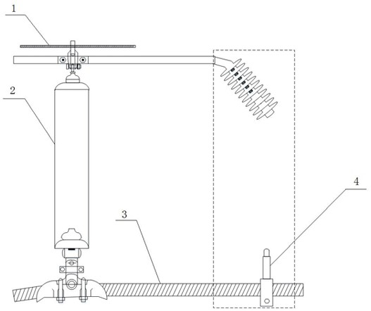
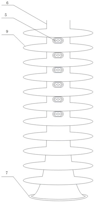
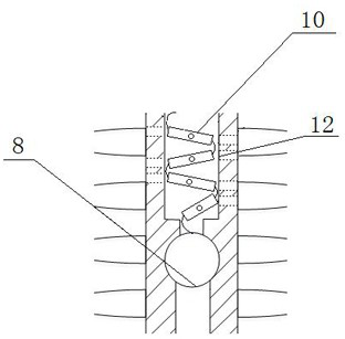
[0050] A trumpet type recoil compression arc extinguishing lightning protection device, comprising a device main body 6; the outer surface of the device main body 6 is provided with several skirts 9; the interior of the device main body 6 is hollow, and the inner diameter of the device main body 6 And the outer diameter gradually increases from top to bottom, so that the main body 6 of the device is trumpet-shaped, and the arc ball I8 is embedded in the main body 6 of the device. The arc ball I8 divides the main body 6 of the device into two parts, and the upper part The space is provided with an arc extinguishing path composed of several sections of arc extinguishing pipes 10 arranged obliquely from top to bottom; the lower part of the main body of the device is a recoil pipe in a semi-enclosed space; the arc extinguishing pipe 10 is provided with a guide Arc ball III11; the ends of two adjacent arc extinguishing pipes are connected by conductive connectors, and the end of the...

Embodiment 2

[0060] The difference between this embodiment and Embodiment 1 is that a plurality of metal rings 15 and small platforms 16 are sequentially installed in the lower half space inside the device main body 6 from top to bottom; Shape, the metal ring 15 is installed on the small platform 16, and the outer surface of the metal ring 15 is close to the inner wall surface of the device main body 6, wherein a small platform is installed above the recoil injection port 7 at the bottom of the device main body. The metal rings 15 are equidistantly arranged in the lower half space of the main body of the device.

[0061] The outer diameter of the metal ring 15 is closely attached to the inner diameter of the device main body 6, and its position is fixed by a small platform 16 to avoid displacement of the metal ring 15 during the recoil process; the metal conductivity of the metal ring 15 is used to ensure that the arc can enter the device main body 6 smoothly, Realize the recoil function, ...

Embodiment 3

[0063] The difference between this embodiment and Embodiment 1 is that the conductive connector is a three-way pipe. The tee pipe 13 is provided with two arc balls II 14 inside; an air gap is provided between the two arc balls II, and the length of the air gap is exactly the diameter of the radial pipe of the tee pipe 13 . The radial nozzle of the three-way pipe 13 is close to the inner wall surface of the main body of the device, and a corresponding compressed air injection channel is provided on the side wall of the main body of the device.

[0064] The arc ball II 14 is a spherical structure. When the arc enters the tee pipe 13, the jet airflow formed at the middle injection port of the tee pipe 13 acts on the arc to realize horizontal blowing. Since the device includes the arc extinguishing pipe 10 and the tee pipe 13, it can realize Horizontal and vertical blowing of the arc.


PUM


Abstract

The invention discloses a horn-shaped recoil type compression arc extinguishing lightning protection device. A plurality of skirt edges are arranged on the outer surface of a device main body, the device main body is gradually increased from top to bottom and is horn-shaped, and an arc guide ball I is embedded in the device main body and divides the device main body into two parts of space. An arcextinguishing path composed of arc extinguishing pipelines is arranged in the upper half space, arc guide balls III are arranged in the arc extinguishing pipelines, the ends of every two adjacent arcextinguishing pipelines are connected through a conductive connecting piece, and the tail end of the last arc extinguishing pipeline is electrically connected with an arc guide ball I; and a compressed airflow injection channel and a compressed airflow injection port are formed in the side wall of the device main body. The device is simple in structure, a filling effect of a narrow pipe of a horn-shaped recoil pipe and a transverse and longitudinal blowing effect of the compressed pipeline on an arc are adopted, a density difference and a temperature difference can be better generated, a stronger recoil effect can be generated on the arc with large energy, the arc can be better cut off, the arc energy is greatly reduced, and arc extinguishing is facilitated.

Description

technical field [0001] The invention belongs to the technical field of electric power fittings for power transmission and distribution overhead lines, and relates to a horn-shaped recoil compression arc-extinguishing lightning protection device. Background technique [0002] In my country, the distribution of power energy and load centers is very uneven, mainly based on coal power generation. Most of the coal resources are concentrated in the northwest region, and the exploitable hydropower resources are mainly concentrated in the west and central regions, while my country's load centers are concentrated in the eastern coastal areas, Beijing-Tianjin-Tangshan and central developed regions. This determines that in order to solve the power problem of the load center in our country, we must vigorously develop hydropower and thermal power generation while building cross-regional, large-capacity and long-distance energy transmission channels. [0003] With the continuous increase...

Claims


Application Information

Patent Timeline
Patent Type & Authority Applications(China)
IPC IPC(8): H01T1/02H01T1/08H01T4/08H01T4/10H01B17/48H01B17/46
CPCH01T1/02H01T1/08H01T4/08H01T4/10H01B17/48H01B17/46Y02P10/20
Inventor 王嬿蕾王巨丰黄上师李籽剑孔佳琦
Owner 王嬿蕾
Why Eureka
Try Eureka