Supercharge Your Innovation With Domain-Expert AI Agents!

Polymer coating mixing machine

A technology of mixers and polymers, applied in the direction of mixers, shaking/oscillating/vibrating mixers, mixer accessories, etc., can solve problems such as slipping

Inactive Publication Date: 2020-12-22
蒋平
View PDF0 Cites 1 Cited by
  • Summary
  • Abstract
  • Description
  • Claims
  • Application Information

AI Technical Summary

Problems solved by technology

[0004] Since the center of the clamped paint cover is lower than the surrounding, the clamped plate is flat, so when clamping with the top cover of the shaker tank, only the edge ring is connected and fixed, and it is easier to slip when shaking vigorously

Method used


Image

  • Polymer coating mixing machine
  • Polymer coating mixing machine
  • Polymer coating mixing machine

Examples


Embodiment 1

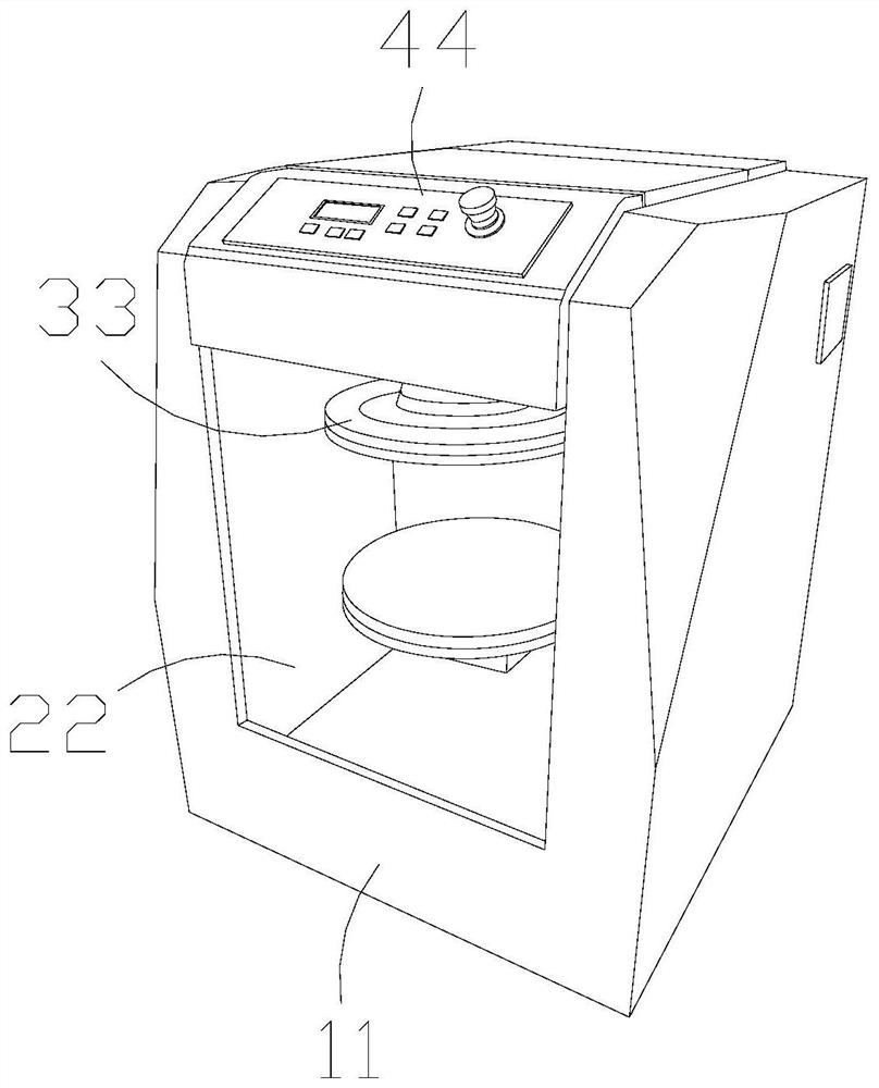
[0032] as attached figure 1 to attach Figure 6 Shown:

[0033] The present invention provides a polymer paint mixer, the structure of which includes a box body 11, an inner grid 22, a splint 33, and an operating panel 44, the inner grid 22 and the box body 11 are an integrated structure, and the splint 33 is installed on Inside the inner grid 22 , the operation panel 44 is welded to the outer surface of the box body 11 .

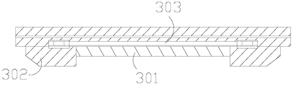
[0034] The splint 33 includes a middle rod 301, a support block 302, and an inner channel 303. Both ends of the middle rod 301 are installed between the two support blocks 302, and the top ends of the support block 302 are embedded in the inner channel 303 and are flexibly connected. .

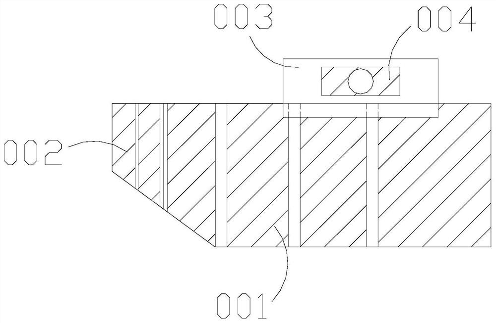
[0035] Wherein, the supporting block 302 includes a pushing block 001, a pressing block 002, an extending block 003, and a sliding block 004. The upper end is fixedly connected, the press block 002 is connected to the side of the push block 001, the press block 002 is a...

Embodiment 2

[0042] as attached Figure 7 to attach Figure 9 Shown:

[0043] Wherein, the middle pole 301 includes a spacer w11, a spacer bar w12, and a rubber support block w13, the spacer w11 is fixed on the outer surface of the rubber support block w13, and the spacer w12 is attached to the outer surface of the rubber support block w13, The support rubber block w13 has a trapezoidal structure. The support rubber block w13 has its own toughness, and when the force on both sides is stressed, it plays the role of extrusion force. The spacer w12 separates the force-bearing part from the fixed parts.

[0044]Wherein, the supporting rubber block w13 includes a pressing arc 111, an insulating strip 112, and an outer limit layer 113. The insulating strip 112 is attached to the outer surface of the pressing arc 111, and the end of the insulating bar 112 is far away from the pressing arc 111. Connected with the outer limit layer 113, the force barrier bar 112 has an arc-shaped structure, the ...


PUM


Abstract

A disclosed polymer coating mixing machine structurally comprises a box body, an inner grid, a clamping plate and an operation plate, the inner grid and the box body are of an integrated structure, the clamping plate is installed in the inner grid, the operation plate is welded to the outer surface of the box body, and a notch in a cover of the operation plate can extrude a supporting block in thedirection of a middle rod, so that the supporting block can be stressed to abut against the edge of the notch; an extending block at the upper end can drive a sliding block to slide along an inner channel to limit the whole moving position, the middle is separated by a force separating block, a rubber head located at the end is bent and stressed, extrusion force exerted on a connection portion gives play to a concentric-square-shaped effect, and when a notch is formed in a cover body, the notch of the cover body can be clamped and fixed to prevent the cover body from sliding out during shaking; and rubber supporting blocks are separated by separation blocks through separation strips, the middle portions of the rubber supporting blocks, of which two sides bear force, are separated by forceseparation strips, when an pressing arc is stressed, a soft block can be pressed to deform, external force is in a counter-force state, and when the cover body is clamped and fixed through stress blocks, the supporting force on clamping and fixing blocks can be achieved.

Description

technical field [0001] The invention belongs to the field of mixers, and more specifically relates to a polymer paint mixer. Background technique [0002] When the color of polymer paint needs to be mixed, the primary color is placed in the assembly barrel, and the barrel body needs to be clamped by a leveler, and the inner paint can be evenly mixed together through high-speed shaking, in order to improve the sealing , the lid of the barrel is in the shape of a concave perimeter. [0003] Based on the above-mentioned inventor's discovery, the existing polymer coating mixer mainly has the following deficiencies, such as: [0004] Because the center of the clamped paint cover is lower than the surroundings, and the clamped plate is flat, so when clamping with the top cover of the shaking tank body, only the edge ring is connected and fixed with it, and it is easier to slip when shaking vigorously. [0005] Therefore need to propose a kind of polymer paint mixer. Contents o...

Claims


Application Information

Patent Timeline
Patent Type & Authority Applications(China)
IPC IPC(8): B01F11/00B01F15/00
CPCB01F31/201B01F35/55B01F2101/30
Inventor 蒋平
Owner 蒋平
Features
  • R&D
  • Intellectual Property
  • Life Sciences
  • Materials
  • Tech Scout
  • Unparalleled Data Quality
  • Higher Quality Content
  • 60% Fewer Hallucinations
Learn More