A porous confluence hedging energy dissipation structure for hydraulic structures and its implementation method

A hydraulic structure and energy dissipation technology, applied in construction, water conservancy engineering, marine engineering and other directions, can solve the problems of local negative pressure of auxiliary facilities, cavitation damage, violent impact damage of auxiliary energy dissipation facilities, etc., to improve energy dissipation. Efficiency, prominent energy dissipation effect, enhanced water turbulence effect

Active Publication Date: 2022-01-18
重庆江源工程勘察设计有限公司
View PDF0 Cites 0 Cited by
  • Summary
  • Abstract
  • Description
  • Claims
  • Application Information

AI Technical Summary

Problems solved by technology

[0003] Existing engineering practice has proved that when the water flow rate is large, the side walls of auxiliary facilities are prone to local negative pressure, resulting in cavitation damage, and auxiliary energy dissipation facilities are often damaged by violent impacts. In terms of steady flow and energy dissipation rate It is difficult to meet the requirements of flood discharge and energy dissipation

Method used


Image

  • A porous confluence hedging energy dissipation structure for hydraulic structures and its implementation method
  • A porous confluence hedging energy dissipation structure for hydraulic structures and its implementation method
  • A porous confluence hedging energy dissipation structure for hydraulic structures and its implementation method

Examples


Embodiment Construction

[0031]The following will clearly and completely describe the technical solutions in the embodiments of the present invention with reference to the accompanying drawings in the embodiments of the present invention. Obviously, the described embodiments are only some, not all, embodiments of the present invention. Based on the embodiments of the present invention, all other embodiments obtained by persons of ordinary skill in the art without making creative efforts belong to the protection scope of the present invention.

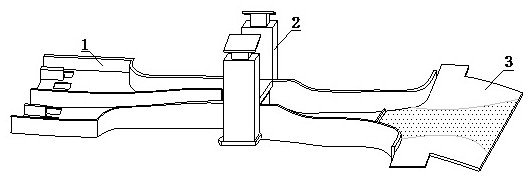
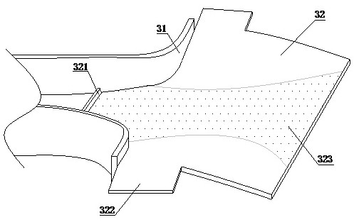
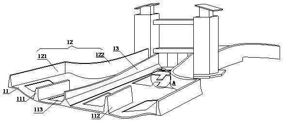
[0032] refer to figure 1 , image 3 , Figure 4 and Figure 8-9 , a kind of porous confluence hedging energy dissipation structure for a hydraulic structure, comprising a water inlet 1, an intermediate gate 2 and a water outlet 3, an intermediate gate 2 is installed between the water inlet 1 and the water outlet 3, and the water inlet 1 includes a water inlet bearing base plate 11, a protective side wall 12 and a partition wall 13, and both sides of the wate...


PUM


Abstract

The invention discloses a porous confluence hedging energy dissipation structure for a hydraulic structure and an implementation method, which comprises a water inlet part, an intermediate gate and a water outlet part, and an intermediate gate is installed between the water inlet part and the water outlet part. The first diversion trapezoidal pier, the second diversion trapezoidal pier and the partition wall of the energy dissipation structure separate the water inlet from two major water inlets, and each water inlet is composed of a set of main holes and side holes, consisting of This makes the entire water inlet into a multi-hole water inlet shape, and due to the vertical impact of the longitudinal water flow discharged from the main hole, the opposite impact of the water flow discharged from the side holes close to the two walls is weakened to a certain extent. At this time, the phase-staggered collision energy dissipation is The main energy dissipation method, in order to ensure the safety of the structure, the main hole and the side hole need to be opened and closed synchronously at any time during the operation of the project, so as to prevent the horizontal water flow from impacting on the protective side wall when one side hole is opened alone, and the longitudinal flow discharged from the first main hole The water flow collides orthogonally with the horizontal "water wall" formed by the vertical deflection that is discharged near the side hole of the side wall at the narrow section of the beam.

Description

technical field [0001] The invention relates to the technical field of hydraulic engineering, in particular to a porous confluence hedging energy dissipation structure for hydraulic structures. Background technique [0002] In the construction of water conservancy and hydropower projects, gravity dams and gate dams are commonly used types of overflow dams. Due to the need for flood discharge and energy dissipation, a stilling pool of a certain scale is often built behind the overflow dam. The strong tumbling caused by the hydraulic jump and a large amount of air entrainment are used to dissipate energy. With the improvement of modern dam-building technology, the overall scale of dam construction is developing towards the trend of high water head and large flow, and the size of the downstream stilling basin has also increased sharply. The engineering practice also proves that with the increase of the height of the dam, the damage rate and damage degree of the stilling basin ...

Claims


Application Information

Patent Timeline
Patent Type & Authority Patents(China)
IPC IPC(8): E02B8/06E02B8/00
CPCE02B8/06E02B8/00
Inventor 王涛
Owner 重庆江源工程勘察设计有限公司
Why Eureka
Try Eureka