
Profile steel reinforced light steel keel partition wall and construction method

A light steel keel and reinforced technology, which is applied to walls, building components, buildings, etc., can solve the problems of hollowing out in the middle of the installation structure and low strength of the partition wall structure, and achieve the effect of improving the compressive capacity

Active Publication Date: 2020-12-22
北京挚诚华腾建设工程有限公司
View PDF7 Cites 3 Cited by
  • Summary
  • Abstract
  • Description
  • Claims
  • Application Information

AI Technical Summary

Problems solved by technology

[0004] In view of the related technologies mentioned above, the inventor believes that there are the following defects: the middle part of the installation structure of the traditional light steel keel partition wall is hollowed out, which will lead to low structural strength of the partition wall after installation

Method used


Image

  • Profile steel reinforced light steel keel partition wall and construction method
  • Profile steel reinforced light steel keel partition wall and construction method
  • Profile steel reinforced light steel keel partition wall and construction method

Examples


Embodiment 1

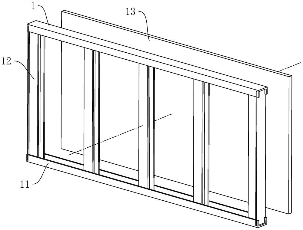
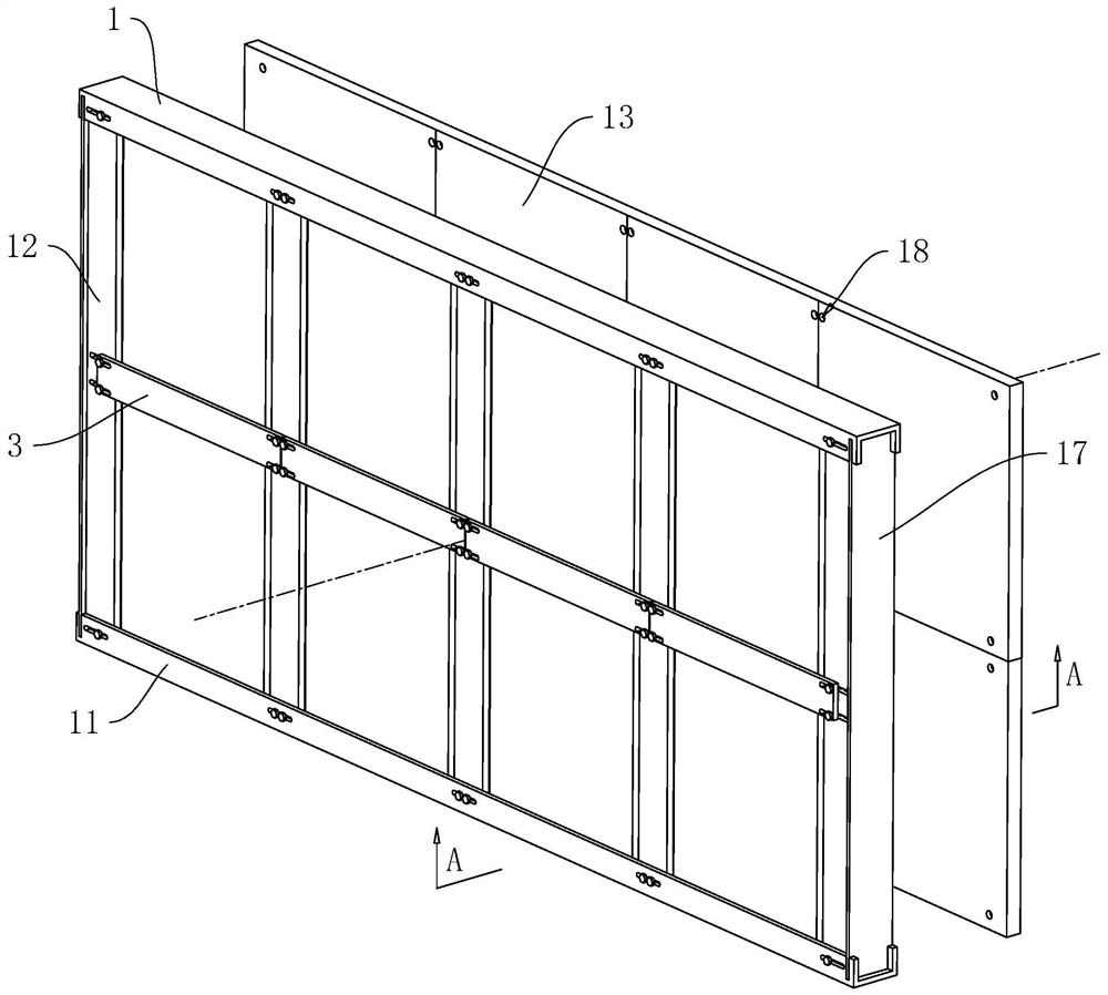
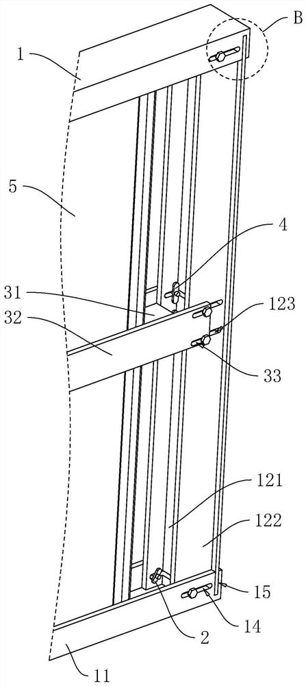
[0046] refer to figure 2 as well as image 3 A steel-reinforced light steel keel partition wall includes a sky keel 1, a ground keel 11, five vertical keels 12 and several wall surfaces 13, the sky keel 1 is fixedly connected to the ceiling, and the ground keel 11 is fixedly connected to the ground. A vertical keel 12 is installed between the sky keel 1 and the ground keel 11 through the second fixing member 2, and two vertically distributed support layers 5 are arranged between two adjacent vertical keels 12, and two adjacent support layers A supporting piece 3 is arranged between the layers 5, and the supporting piece 3 and the vertical keel 12 are connected to each other through the first fixing piece 4. Several walls 13 are arranged on the vertical wall formed by the sky keel 1, the ground keel 11, and the five vertical keels 12. to the plane.

[0047] refer to image 3 as well as Figure 4 The sky keel 1 and the ground keel 11 are both C-shaped steel beams. The verti...

Embodiment 2

[0059] A construction method for a section steel reinforced light steel keel partition wall, comprising the following steps:

[0060] S1: Positioning and setting out;

[0061] S2: Install the sky keel 1 and the ground keel 11;

[0062] S3: Place the first vertical keel 12 between the sky keel 1 and the ground keel 11 and pass the second fixing member 2 through the first waist hole 123 and the third waist hole 14 on the first vertical keel 12, Place several support members 3 on the vertical keel 12, then pass the first fixing member 4 through the first waist-shaped hole 123 and the second waist-shaped hole 33 on the first vertical keel 12, so that the support member 3 is pre-positioned at On the vertical keel 12, put the support plate into several frames formed by the support member 3, the vertical keel 12, the sky keel 1 and the ground keel 11;

[0063] S4: Place the second vertical keel 12 between the sky keel 1 and the ground keel 11 and pass the second fixing member 2 throu...


PUM


Abstract

The invention relates to a profile steel reinforced light steel keel partition wall and a construction method. The profile steel reinforced light steel keel partition wall comprises a top keel, a bottom keel, a plurality of vertical keels and a plurality of wall surfaces arranged on a vertical surface formed by the top keel, the bottom keel and the vertical keels, wherein the top keel is used forbeing connected with a ceiling, the bottom keel is used for being connected with the ground, the upper ends of the vertical keels are arranged on the top keel, and the lower ends of the vertical keelsare arranged on the bottom keel; and a plurality of supporting layers distributed in the vertical direction are arranged between every two adjacent vertical keels, and the supporting layers are vertically arranged and are parallel to one another. The profile steel reinforced light steel keel partition wall has the effect of improving the structural strength of the partition wall.

Description

technical field [0001] The application relates to the field of construction engineering, in particular to a section steel-reinforced light steel keel partition wall and a construction method. Background technique [0002] With the development of modern architecture and the application of new building materials, the non-load-bearing walls of buildings have gradually developed from traditional masonry solid clay bricks to various lightweight materials or blocks. The light steel keel wall is a light steel keel skeleton, which is composed of a non-load-bearing wall system with a hollow center and two flat ends. It has the advantages of light weight, non-combustibility, sound insulation, heat insulation, good seismic performance, simple construction, and short construction period. , suitable for industrial and civil buildings, especially non-load-bearing partition walls in new construction, expansion or reconstruction of high-rise buildings. [0003] refer to figure 1 The relat...

Claims


Application Information

Patent Timeline
Patent Type & Authority Applications(China)
IPC IPC(8): E04B2/74E04B2/76
CPCE04B2/7409E04B2/76
Inventor 李世平高玉峰
Owner 北京挚诚华腾建设工程有限公司
Learn More