
Permanent magnet device and magnetron sputtering equipment

A permanent magnet device and permanent magnet technology, applied in the direction of permanent magnets, sputtering coatings, magnets, etc., can solve the problems of affecting the coating quality, uneven metal film thickness, and difficulty in ensuring accuracy, and achieve simple operation of angle adjustment, Effect of improving coating quality and ensuring accuracy

Inactive Publication Date: 2020-12-22
BETONE TECH SUZHOU INC
View PDF6 Cites 0 Cited by
  • Summary
  • Abstract
  • Description
  • Claims
  • Application Information

AI Technical Summary

Problems solved by technology

Most of the permanent magnet components are fixed, and the wafer coating has very high requirements on the thickness and uniformity of the metal film to be coated. The direction of the magnetic field generated by the fixed permanent magnet components cannot effectively meet the actual sputtering requirements. This will lead to uneven thickness of the metal film coated on the wafer surface, which will affect the quality of the coating
[0004] The permanent magnet assembly of a small number of magnetron sputtering equipment can rotate in the horizontal plane, but the angle of the permanent magnet assembly remains unchanged when rotating. If you have to change the angle of the permanent magnet assembly, you can only adjust it manually. It is very cumbersome to manually adjust the angle of the permanent magnet assembly, and the accuracy is difficult to guarantee. Moreover, it is difficult to ensure that the driving mechanism drives the permanent magnet assembly to form a stable rotating magnetic field after the angle adjustment of the permanent magnet assembly.

Method used


Image

  • Permanent magnet device and magnetron sputtering equipment
  • Permanent magnet device and magnetron sputtering equipment
  • Permanent magnet device and magnetron sputtering equipment

Examples


Embodiment Construction

[0030]In order to make the objectives, technical solutions, and advantages of the embodiments of the present invention clearer, the technical solutions in the embodiments of the present invention will be described clearly and completely in conjunction with the accompanying drawings in the embodiments of the present invention. Obviously, the described embodiments It is a part of the embodiments of the present invention, not all the embodiments. The components of the embodiments of the present invention generally described and shown in the drawings herein may be arranged and designed in various different configurations. Therefore, the following detailed description of the embodiments of the present invention provided in the accompanying drawings is not intended to limit the scope of the claimed invention, but merely represents selected embodiments of the present invention. Based on the embodiments of the present invention, all other embodiments obtained by those of ordinary skill in t...


PUM


Abstract

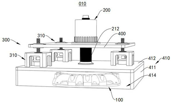
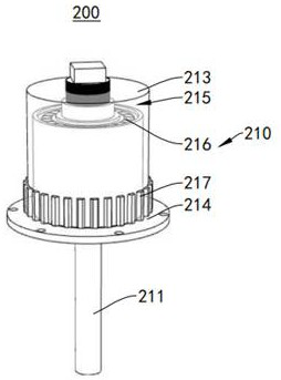
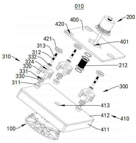
The invention relates to the field of semiconductor manufacturing equipment, in particular to a permanent magnet device and magnetron sputtering equipment. The permanent magnet device comprises a permanent magnet assembly, a first driving mechanism and a second driving mechanism, and the first driving mechanism is in transmission connection with the permanent magnet assembly and used for driving the permanent magnet assembly to rotate to form a rotating magnetic field; the second driving mechanism is in transmission connection with the first driving mechanism and used for driving the first driving mechanism to move to adjust the included angle of the permanent magnet assembly relative to the horizontal plane. The permanent magnet device is easy to operate when the angle of the permanent magnet assembly is adjusted, the accuracy can be guaranteed, and the first driving mechanism can also be used for driving the permanent magnet assembly to stably form a rotating magnetic field after theangle of the permanent magnet assembly is adjusted. The magnetron sputtering equipment provided with the permanent magnet device provided by the invention can be used for uniformly coating a wafer soas to ensure the coating quality of the wafer.

Description

Technical field[0001]The invention relates to the field of semiconductor manufacturing equipment, in particular to a permanent magnet device and magnetron sputtering equipment.Background technique[0002]Magnetron sputtering is a kind of physical vapor deposition (Physical Vapor Deposition, PVD). The general sputtering method can be used to prepare a variety of materials such as metals, semiconductors, and insulators, and has the advantages of simple equipment, easy control, fast sputtering rate, large coating area and strong adhesion. Magnetron sputtering introduces a magnetic field on the surface of the target cathode to allow electrons to form a spiral trajectory around the lines of magnetic force. The magnetic field confines the charged particles to increase the ionization rate of the gas and increase the plasma density to increase the sputtering rate.[0003]The magnetic field introduced by the magnetron sputtering equipment is realized by permanent magnet components. Most permanen...

Claims


Application Information

Patent Timeline
Patent Type & Authority Applications(China)
IPC IPC(8): H01F7/02C23C14/35H01L21/67
CPCC23C14/35H01F7/0278H01L21/67207
Inventor 潘学勤宋维聪周云
Owner BETONE TECH SUZHOU INC
Learn More