Supercharge Your Innovation With Domain-Expert AI Agents!

Cavity-backed patch antenna based on substrate integrated waveguide

A patch antenna and cavity-backed technology, which is applied in the direction of antenna, antenna coupling, antenna grounding switch structure connection, etc., can solve the problem that the antenna is easily affected by surface waves, etc., and achieve the effect of easy processing and integration

Inactive Publication Date: 2020-12-22
SUN YAT SEN UNIV
View PDF1 Cites 0 Cited by
  • Summary
  • Abstract
  • Description
  • Claims
  • Application Information

AI Technical Summary

Problems solved by technology

The invention adopts the dielectric integrated waveguide technology, which solves the problem that the traditional microstrip patch antenna is easily affected by surface waves, and has the characteristics of easy integration and processing; plate, this structure enables a first-order cavity mode, a second-order cavity mode and a second-order patch mode of a small conductive plate to couple, thereby realizing the broadband characteristics of the triple resonance

Method used


Image

  • Cavity-backed patch antenna based on substrate integrated waveguide
  • Cavity-backed patch antenna based on substrate integrated waveguide
  • Cavity-backed patch antenna based on substrate integrated waveguide

Examples


Embodiment

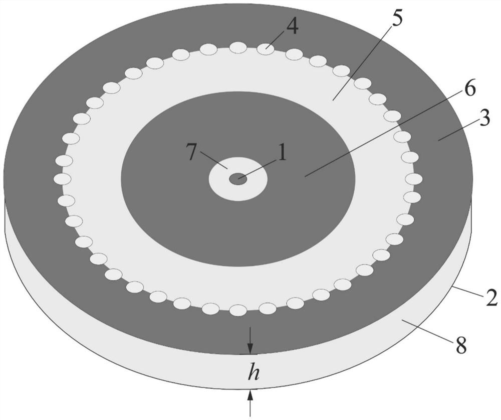
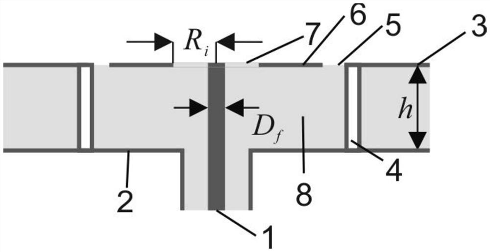
[0037] Such as Figure 1-Figure 3 As shown, a cavity-backed patch antenna based on a substrate integrated waveguide includes a feeding probe 1, a metal floor 2, a large upper metal plate 3, a short-circuit via hole 4, a small upper metal plate 6 and a dielectric plate 8. The metal floor 2 and the upper metal plates 3 and 6 are respectively located on the upper and lower surfaces of the medium plate 8, the large upper metal plate 3 has a circular hollow 5, and the small upper metal plate 6 has a There is a circular hollow 7 , the short-circuit vias 4 are arranged along the edge of the hollow 5 , and a feeding probe 1 is arranged at the center of the hollow 5 , and the feeding probe penetrates the dielectric plate 8 longitudinally.

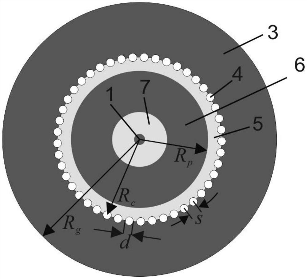
[0038] In this example, if figure 2 As shown, the large upper metal plate 3 has a circular hollow groove 5, the radius of the large upper metal plate 3: R g , radius of empty slot 5: R c .

[0039] In this example, if figure 2 As shown, the s...


PUM

PropertyMeasurementUnit
Radiusaaaaaaaaaa
Radiusaaaaaaaaaa
Radiusaaaaaaaaaa

Abstract

In order to obtain a better omnidirectional antenna, the invention discloses a cavity-backed patch antenna based on a substrate integrated waveguide, which comprises a dielectric plate, a first conductive plate, a second conductive plate and a feed probe, the first conductive plate, the second conductive plate and the dielectric plate are cylindrical, and one bottom surface of the first conductiveplate is connected with one bottom surface of the dielectric plate. The area of the section of the first conductive plate is equal to that of the section of the dielectric plate, and the circle center of the first conductive plate is coaxial with that of the dielectric plate; a first circular hole is formed in the conductive plate, and the circle center of the first circular hole, the circle center of the second circular hole and the circle center of the dielectric plate are coaxial; a plurality of short-circuit via holes are formed in the edge of the first circular hole in a surrounding manner; one bottom surface of the second conductive plate is connected with one bottom surface of the dielectric plate, the radius of the section of the second conductive plate is smaller than that of thefirst circular hole, and the circle center of the second conductive plate is coaxial with the circle center of the dielectric plate; a second circular hole is formed in the second conductive plate; the feed probe is arranged at the center of the antenna and longitudinally penetrates through the dielectric plate.

Description

technical field [0001] The invention relates to the field of antennas, in particular to a cavity-backed patch antenna based on a substrate integrated waveguide. Background technique [0002] The omnidirectional antenna is a kind of antenna commonly used in wireless communication. It can achieve omnidirectional radiation in azimuth, allowing multiple users to use it at the same time. Existing omnidirectional antennas include monopole antennas and microstrip patch antennas. A monopole antenna is easy to fabricate, but it is thicker and has a smaller bandwidth. The microstrip patch antenna is easy to fabricate, and can achieve large bandwidth by loop coupling, loading short-circuit nails and double-layer dielectric boards. However, the performance of the microstrip patch antenna is easily affected by surface waves and the external environment. Due to the cavity-back structure, the cavity-backed antenna is less affected by surface waves. However, most of the existing cavity...

Claims


Application Information

Patent Timeline
IPC IPC(8): H01Q1/38H01Q1/50H01Q1/52H01Q5/10H01Q5/307
CPCH01Q1/38H01Q1/50H01Q1/52H01Q5/10H01Q5/307
Inventor 蔡双棋刘菊华
Owner SUN YAT SEN UNIV
Features
  • R&D
  • Intellectual Property
  • Life Sciences
  • Materials
  • Tech Scout
  • Unparalleled Data Quality
  • Higher Quality Content
  • 60% Fewer Hallucinations
Learn More