Equipment power distribution control box

A technology for power distribution control and equipment, applied in seismic equipment, electrical components, substation/switch layout details, etc., can solve problems such as weak concentrated load capacity, slag cracking signal interference and fluctuation, and small thickness of cold-rolled formed steel walls. Achieve the effect of reducing the impact force of installation, good operation signal and increasing load force

Inactive Publication Date: 2020-12-22
庄小梅
View PDF0 Cites 0 Cited by
  • Summary
  • Abstract
  • Description
  • Claims
  • Application Information

AI Technical Summary

Problems solved by technology

[0004] The main purpose of the present invention is to overcome the deficiencies of the prior art and provide an equipment power distribution control box to solve the problem that the thickness of the cold-rolled formed steel wall is small, and the corners where the plates are connected are weak in bearing local concentrated loads. Installing large inclusions will increase edge cracks, resulting in uneven internal flow and heat transfer, and cracked slag will increase signal interference fluctuations

Method used


Image

  • Equipment power distribution control box
  • Equipment power distribution control box
  • Equipment power distribution control box

Examples


Embodiment 1

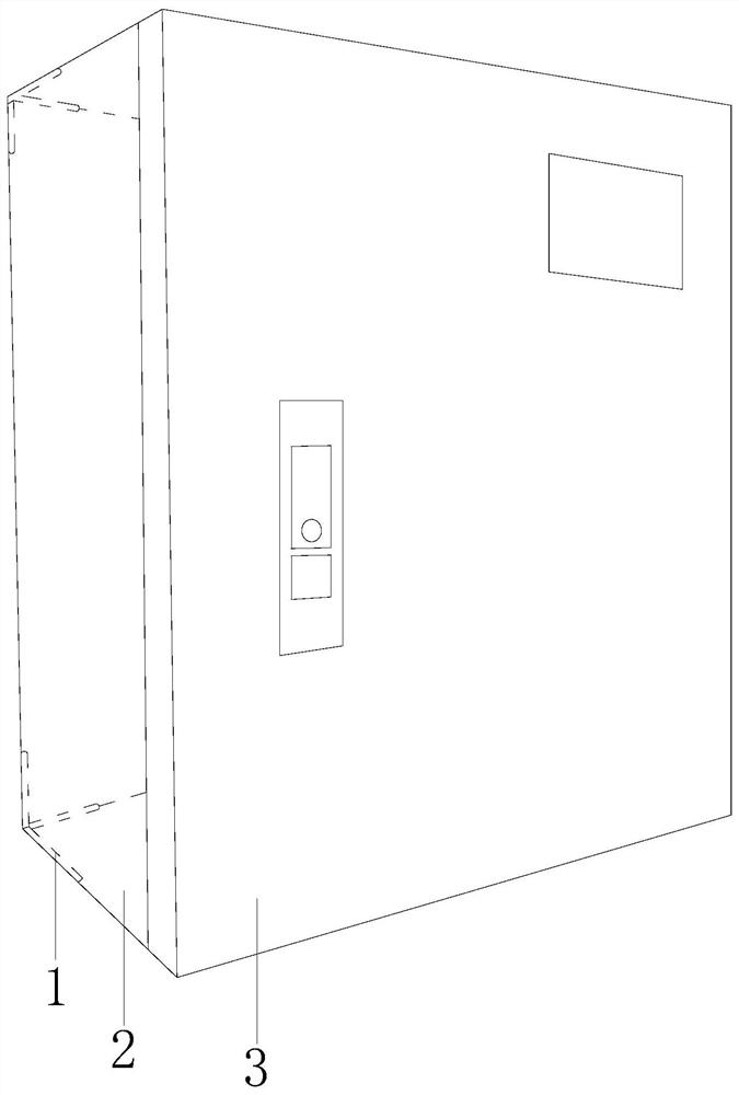
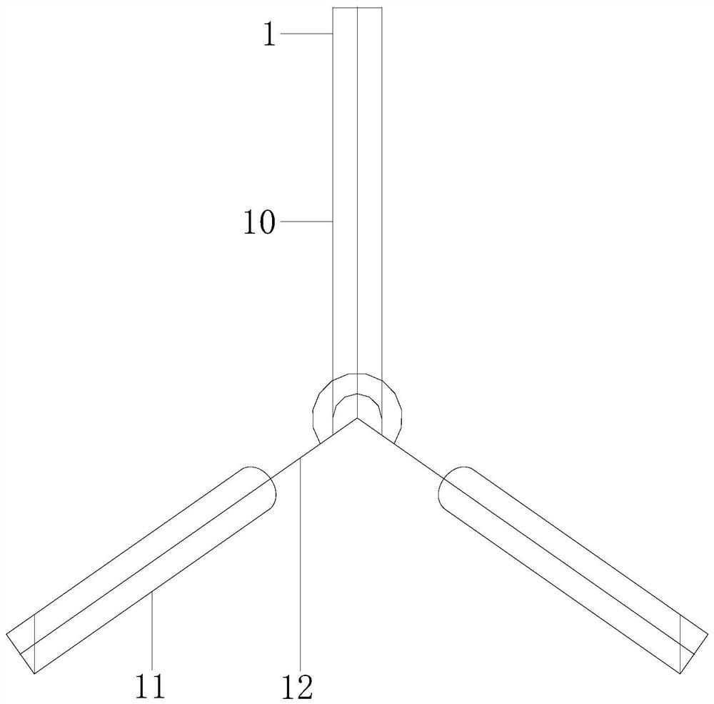
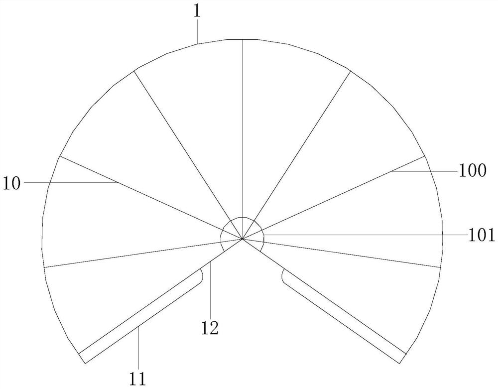
[0027] Example 1 see Figure 1-6 , the present invention provides a technical scheme of equipment power distribution control box: its structure includes an inner angle structure 1, a control box frame 2, and a control box door 3, the inner angle structure 1 is installed inside the control box frame 2, and the element The device is installed inside the control box frame 2, and is driven and assisted by the inner angle structure 1. The control box frame 2 and the control box door 3 are connected by shaft bolts. The inner angle structure 1 is composed of an upper rod structure 10, a side branch structure 11. Composed of tripod bars 12. When the inner angle structure 1 is driven, the upper rod structure 10 is unfolded in a fan-shaped structure, which increases the thickness of the corners of the control box frame 2. The upper rod structure 10 and the side branch structure 11 are installed on the On the tripod bar 12, the upper rod structure 10 includes a movable rod 100 and a mova...

Embodiment 2

[0029] Example 2 see Figure 7 , 8 , the present invention provides a technical solution for equipment power distribution control box: the structure of the side support structure 11 includes an end pad 110, a main part structure 111, and a fan pressure structure 112, and the end pad 110 is bonded to the main part structure 111, The main part structure 111 is track-connected with the fan pressing structure 112. The main part structure 111 includes an integral main part 1110, an upper sliding part 1111, and a bottom sliding rail 1112. The integral main part 1110 is embedded with a bottom sliding rail 1112. The upper slider 1111 is track-connected with the bottom slide rail 1112. The fan pressure structure 112 includes a sectioned inclined support plate 1120, a pressure section cone block 1121, and a circular pad 1122. The sectioned inclined support plate 1120 and the section pressure cone The block 1121 is installed and connected, the section pressure cone block 1121 is glued t...


PUM


Abstract

The invention discloses an equipment power distribution control box, and the box structurally comprises an inner corner structure, a control box frame and a control box door, wherein the inner cornerstructure is installed in the control box frame, the control box frame is connected with the control box door through a shaft bolt, and the inner corner structure is composed of an upper rod structure, a side supporting structure and a tripod strip, wherein the upper rod structure and the side supporting structure are arranged on the tripod strip; the upper rod structure comprises a movable striprod and a movable rod shaft; the movable strip rod is connected with the movable rod shaft, and the movable strip rod is connected with a bottom supporting strip; the movable rod shaft comprises a rodshaft disc, a reinforcing arc cover, a transverse plate and a welding bottom cover, wherein the rod shaft disc is provided with the transverse plate, the reinforcing arc cover and the transverse plate are locked, and the rod shaft disc is provided with the welding bottom cover. The inner corner structure plays a role in assisting in loading, the loading force at the corner of the box frame of thecontrol box is improved, the side supporting structure plays a role in buffering, the installation impact force is reduced, edge cracking is avoided, and the operation signal is good.

Description

technical field [0001] The invention relates to the field of power distribution control boxes, in particular to an equipment power distribution control box. Background technique [0002] The electrical cabinet is a cabinet made of steel to protect the normal operation of components. The materials for electrical cabinets are generally divided into two types: hot-rolled steel plate and cold-rolled steel plate. Compared with hot-rolled steel plate, cold-rolled steel plate is softer and more suitable for electrical appliances. cabinet making. [0003] In the prior art, the thickness of the cold-rolled formed steel wall is small, and the ability to bear local concentrated loads at the corners of the joints of the plates is weak. The installation of large inclusions will increase the edge cracks, resulting in uneven internal flow and heat transfer, and cracks. The slag will increase the interference fluctuation of the signal. Contents of the invention [0004] The main purpose...

Claims


Application Information

Patent Timeline
Patent Type & Authority Applications(China)
IPC IPC(8): H02B1/46H02B1/48H02B1/54
CPCH02B1/46H02B1/48H02B1/54
Inventor 庄小梅
Owner 庄小梅
Why Eureka
Try Eureka