Stamping die for axle tube parts

A technology for stamping and parts, applied in the field of stamping and processing molds for shaft and tube parts, can solve the problems of debris affecting stamping, parts easily toppling, etc., to achieve uniform force, convenient mold withdrawal, and reduce dangerous operations.

Active Publication Date: 2020-12-25
东莞市华源晟五金制品有限公司
View PDF5 Cites 0 Cited by
  • Summary
  • Abstract
  • Description
  • Claims
  • Application Information

AI Technical Summary

Problems solved by technology

[0005] The purpose of the present invention is to provide a stamping mold for shaft tube parts to solve the problem that the debris on the lower mold base affects the stamping and the parts are easy to fall when the mold is withdrawn

Method used


Image

  • Stamping die for axle tube parts
  • Stamping die for axle tube parts

Examples


Embodiment

[0033] The following will clearly and completely describe the technical solutions in the embodiments of the present invention with reference to the accompanying drawings in the embodiments of the present invention. Obviously, the described embodiments are only some, not all, embodiments of the present invention. Based on the embodiments of the present invention, all other embodiments obtained by persons of ordinary skill in the art without making creative efforts belong to the protection scope of the present invention.

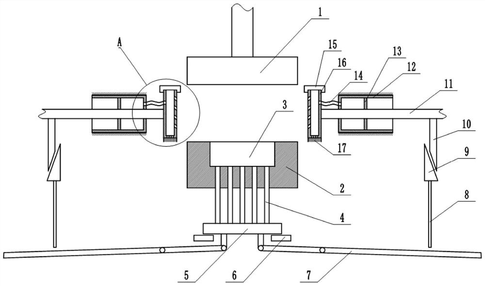
[0034] Such as figure 1 As shown, a stamping processing mold for shaft tube parts includes a frame on which a lower mold base 2 is fixed, and an upper mold base 1 located above the lower mold base 2 is vertically slidably connected to the frame, and the upper mold base 1 The downward movement to realize punching is a prior art, and how the upper die base 1 moves downward will not be repeated in this application. The lower mold base 2 is provided with a mold c...


PUM


Abstract

The invention belongs to the field of part machining, and particularly discloses a stamping die for axle tube parts. The stamping die for the axle tube parts comprises a rack, a lower die base is fixed to the rack, an upper die base located above the lower die base is vertically connected to the rack in a sliding mode, clamping plates are transversely connected to the positions, located on the twosides of the upper end of the lower die base, of the rack in a sliding mode, gaps are formed between the lower ends of the clamping plates and the upper end of the lower die base, bristles are fixedto the lower ends of the clamping plates, and the lower ends of the bristles abut against the upper end of the lower die base; cavities are formed in the clamping plates, air outlet holes communicating with the cavities are formed in the lower ends of the clamping plates, air outlet one-way valves are mounted in the air outlet holes, air suction holes are formed in the opposite faces of the two clamping plates, the opposite sides of the air suction holes in the two clamping plates incline downwards, air suction one-way valves are mounted in the air suction holes, and through holes communicating with the cavities are formed in the upper ends of the clamping plates; and the upper ends of the clamping plates are detachably connected with blocking covers for blocking the through holes. By theadoption of the scheme, the problems that punching is affected by chippings on the lower die base, and the parts are prone to toppling over during die retreating can be solved.

Description

technical field [0001] The invention belongs to the field of parts processing, and in particular relates to a stamping processing die for shaft tube parts. Background technique [0002] In industrial products, shaft parts are suitable for maintenance operations of one or more CNC machine parts. Shaft parts are one of the typical parts often encountered in hardware accessories. They are mainly used to support transmission parts, transmit torque and Bearing load, according to the different structural forms of shaft parts, it can be divided into solid shafts and hollow shafts (ie pipes). [0003] When the shaft parts are punched by the punching machine, such as when the rocker shaft is headed, the parts will be stuck in the upper or lower die of the punching machine, and the ejector rod is often used to eject the shaft parts when ejecting the mold. , when the shaft parts are ejected, in order to avoid the parts from being dumped and damaged, the operator needs to hold the part...

Claims


Application Information

Patent Timeline
IPC IPC(8): B21D37/10B08B1/00B08B5/04
CPCB21D37/10B08B5/04B08B1/12
Inventor 何泽君颜志勇屈祖祯
Owner 东莞市华源晟五金制品有限公司
Why Eureka
Try Eureka