Automatic induction type multi-angle cutting device for aluminum profile production

An automatic induction, cutting device technology, applied in positioning devices, feeding devices, large fixed members, etc., can solve the problems of low cutting accuracy, low cutting efficiency, inability to achieve multi-angle cutting, etc., to ensure tightness, guarantee The effect of cutting efficiency and cutting accuracy

Inactive Publication Date: 2020-12-25
安徽华深铝业有限公司
View PDF9 Cites 0 Cited by
  • Summary
  • Abstract
  • Description
  • Claims
  • Application Information

AI Technical Summary

Problems solved by technology

[0002] During the production and processing of aluminum profiles, it is necessary to cut the processed aluminum profiles. The existing cutting device cannot realize multi-angle cutting during cutting, and cannot cut out different shapes of cutting surfaces during cutting, resulting in the overall Low production efficiency; and when the cutting device is cutting, the overall automation level is low, resulting in low cutting efficiency and low cutting accuracy

Method used


Image

  • Automatic induction type multi-angle cutting device for aluminum profile production
  • Automatic induction type multi-angle cutting device for aluminum profile production
  • Automatic induction type multi-angle cutting device for aluminum profile production

Examples


Embodiment 1

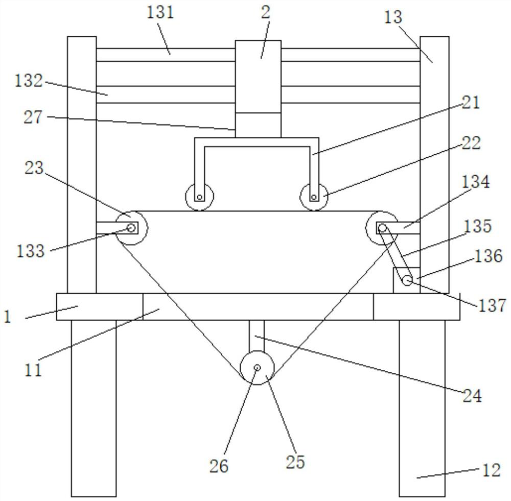
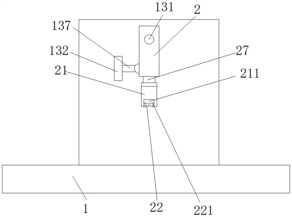
[0027] see Figure 1-2 , an automatic induction multi-angle cutting device for the production of aluminum profiles, including a cutting table 1, the cutting table 1 is provided with symmetrically distributed fixed plates 13, and the inner sides of the fixed plates 13 are provided with rotatable first fixed Pulley 23, the cutting table 1 positioned below the first fixed pulley 23 is provided with a through-type cutting groove 11, and the bottom of the cutting table 1 positioned at the bottom of the cutting groove 11 is provided with a second fixed pulley 25 that can move up and down. A cutting line 28 connected between the first fixed pulley 23 and the second fixed pulley 25 is provided, and a U-shaped cutting frame 21 is arranged above the cutting line 28 between adjacent first fixed pulleys 23, Both ends of the cutting frame 21 are provided with adjustment grooves 211, and a rotatable cutting pulley 22 is arranged in the adjustment groove 211. The cutting pulley 22 is located...

Embodiment 2

[0033] The same as embodiment 1 is not repeated, and the difference with embodiment 1 is:

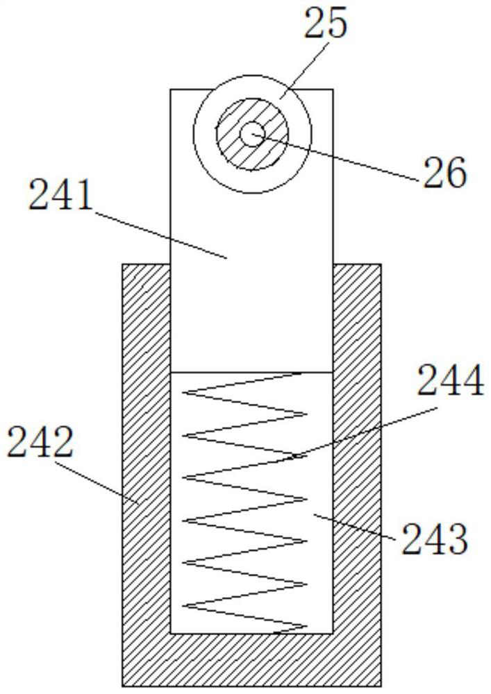
[0034] see image 3 , the retraction mechanism includes a spring 244, one end of the spring 244 is connected to the bottom of the sliding groove 243, and the other end of the spring 244 is connected and fixed to the end of the first positioning rod 241.

[0035] The spring 244 is designed so that when the cutting pulley 22 drives the cutting line 28 to move, the second fixed pulley 25 can move up and down correspondingly, so that the cutting line 28 can effectively cut.

Embodiment 3

[0037] The same as embodiment 1 is not repeated, and the difference with embodiment 1 is:

[0038] see Figure 4 , the retraction mechanism includes a pressure sensor 246 and a third hydraulic rod 245, the chute 243 is provided with a fixedly connected third hydraulic rod 245, the extension end of the third hydraulic rod 245 is connected to the end of the first positioning rod 241 The parts are connected and fixed, and the connection between the third hydraulic rod 245 and the first positioning rod 241 is provided with a pressure sensor 246 for sensing pressure changes, and the pressure sensor 246 is electrically connected with the third hydraulic rod 245 .

[0039] The design of the third hydraulic rod 245 and the pressure sensor 246, through the precise induction of the pressure sensor 246, can adjust the expansion and contraction of the third hydraulic rod 245 in time, which can effectively ensure the tightness of the cutting line 28 during cutting, thereby ensuring overal...


PUM


Abstract

The invention belongs to the technical field of aluminum profile production and particularly relates to an automatic induction type multi-angle cutting device for aluminum profile production. The automatic induction type multi-angle cutting device comprises a cutting table, symmetrically distributed fixed plates are arranged on the cutting table, rotatable first fixed pulleys are arranged on the inner sides of the fixed plates correspondingly, and a through cutting groove is formed in the cutting table. A second fixed pulley capable of moving up and down is arranged at the bottom of the cutting table, a connected cutting line is arranged between the first fixed pulleys and the second fixed pulley, positioning rods are arranged at the two ends of the second fixed pulley and comprise the first positioning rod and the second positioning rod, and a sliding groove slidably connected with the second positioning rod is formed in the first positioning rod. A fixedly connected third hydraulic rod is arranged in the sliding groove, the extending end of the third hydraulic rod is fixedly connected with the end of the first positioning rod, a pressure sensor is arranged at the connecting position of the third hydraulic rod and the first positioning rod, stretching and retracting of the third hydraulic rod are adjusted in time through accurate sensing of the pressure sensor, and therefore the overall cutting efficiency and cutting precision are guaranteed.

Description

technical field [0001] The invention belongs to the technical field of aluminum profile production, in particular to an automatic induction multi-angle cutting device for aluminum profile production. Background technique [0002] During the production and processing of aluminum profiles, it is necessary to cut the processed aluminum profiles. The existing cutting device cannot realize multi-angle cutting during cutting, and cannot cut out different shapes of cutting surfaces during cutting, resulting in the overall Low production efficiency; and when the cutting device is cutting, the overall automation level is low, resulting in low cutting efficiency and low cutting precision. Contents of the invention [0003] Aiming at the problems in the prior art, the object of the present invention is to provide an automatic induction multi-angle cutting device for aluminum profile production. [0004] In order to achieve the above object, the present invention adopts the following...

Claims


Application Information

Patent Timeline
Patent Type & Authority Applications(China)
IPC IPC(8): B23D79/00B23Q3/00B23Q1/25B23Q5/34B23Q11/00
CPCB23D79/00B23Q3/00B23Q1/25B23Q5/34B23Q11/0067
Inventor 林建宝瞿庆广林新军张国庆李登军林建荣林新民李军
Owner 安徽华深铝业有限公司
Why Eureka
Try Eureka