PCB board metal recycling device
A PCB board and metal technology, which is applied in the field of PCB board metal recycling devices, can solve the problems of not realizing automation better
- Summary
- Abstract
- Description
- Claims
- Application Information
AI Technical Summary
Problems solved by technology
Method used
Image

Examples
Embodiment 1
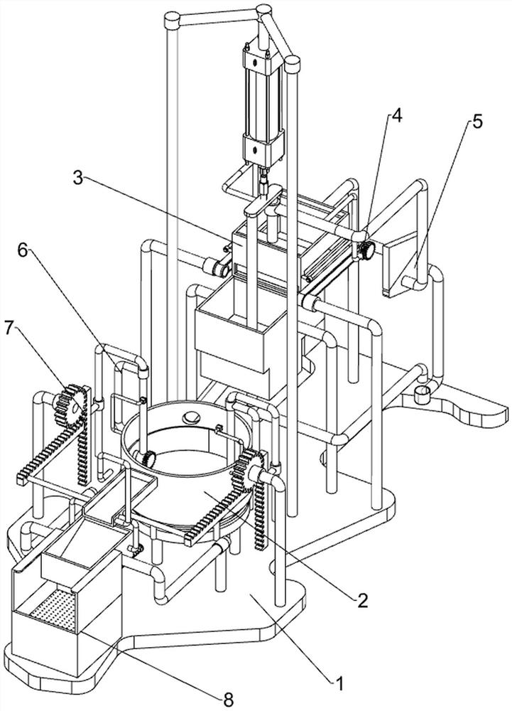
[0075] A kind of PCB board metal recycling device, such as figure 1 As shown, base plate 1, burning mechanism 2 and cutting mechanism 3 are included. Burning mechanism 2 is arranged in the middle of the top of base plate 1. Cutting mechanism 3 is installed on the rear side of bottom plate 1 top. Burning mechanism 2 cooperates with cutting mechanism 3.
[0076] When the worker needs to cut the PCB board into strips, the worker needs to put the PCB board into the cutting mechanism 3 first. When the PCB board is in the cutting mechanism 3, the worker needs to control the cutting mechanism 3 to move up and down. The PCB board is cut into strips. At this time, the worker needs to start the burning mechanism 2, and then the cutting mechanism 3 will transport the PCB strips to the burning mechanism 2. The burning mechanism 2 can melt the PCB strips. At this time, the worker needs to put the PCB liquid Take it out from the burning mechanism 2. After the PCB liquid is taken out by the ...
Embodiment 2
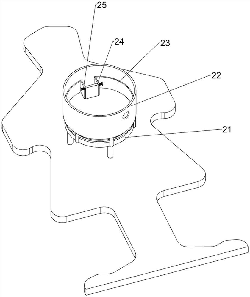
[0078] In a preferred embodiment of the present invention, as figure 2 As shown, the burning mechanism 2 includes a burning platform 21, a fixed frame 22, a feeding and baking frame 23, a rotating and opening plate 24 and a torsion spring 25. The burning platform 21 is placed in the middle of the top of the base plate 1, and the top of the burning platform 21 is fixed with a fixed Frame 22, fixed frame 22 is placed with discharging baking frame 23, and the front side of discharging baking frame 23 is rotatable to be provided with rotating and opening plate 24, and torsion spring 25 is all set on the left and right sides of rotating and opening plate 24 top, torsion spring The two ends of 25 are respectively connected on the baking frame 23 of discharging material and on the plate 24 that is opened by rotation.
[0079] The PCB board cut into strips will slide down into the discharging baking frame 23. When the PCB strips are located in the discharging baking frame 23, the wor...
Embodiment 3
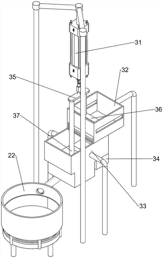
[0081] In a preferred embodiment of the present invention, as figure 1 and Figure 3-Figure 11 As shown, the cutting mechanism 3 includes a cylinder 31, a first cutting and placing frame 32, a second cutting and placing frame 33, a conveying frame 34, a connecting plate 35, a single-sided cutting knife 36 and a multi-sided cutting knife 37, and the rear side of the top of the base plate 1 passes through Bolt is fixed with cylinder 31, and base plate 1 top rear side is welded with first cutting placement frame 32, and base plate 1 top rear side is provided with second cutting placement frame 33, and second cutting placement frame 33 and first cutting placement frame 32 bottom front Side penetrating connection, the lower part of the second cutting frame 33 is penetratingly provided with a conveying frame 34, the bottom end of the telescopic rod of the cylinder 31 is fixedly connected with a connecting plate 35, and the rear side of the bottom end of the connecting plate 35 is fi...
PUM
 Abstract
Description
Claims
Application Information
 - R&D
- Intellectual Property
- Life Sciences
- Materials
- Tech Scout
- Unparalleled Data Quality
- Higher Quality Content
- 60% Fewer Hallucinations
Browse by: Latest US Patents, China's latest patents, Technical Efficacy Thesaurus, Application Domain, Technology Topic, Popular Technical Reports.
© 2025 PatSnap. All rights reserved.Legal|Privacy policy|Modern Slavery Act Transparency Statement|Sitemap|About US| Contact US: help@patsnap.com