
An industrial design material binding device

A technology for industrial design and mounting boards, which is applied in binding and other directions, and can solve the problems of industrial design material binding troubles, increased work intensity, troubles, etc.

Active Publication Date: 2021-09-14
美华建筑设计有限公司
View PDF7 Cites 0 Cited by
  • Summary
  • Abstract
  • Description
  • Claims
  • Application Information

AI Technical Summary

Problems solved by technology

[0006] In order to make up for the deficiencies in the prior art, the present invention proposes a binding device for industrial design materials. The present invention is mainly used to solve the problem that the current industrial design materials need to be manually moved to a suitable position during the process of loading and binding the industrial design materials. Binding the materials, and at the same time, after one side of the cabinet is bound, the cabinet needs to be rotated to bind the other end of the cabinet, which is troublesome. When binding cabinets of different sizes, one side of the cabinet needs to be turned Only when the end surface moves below the binding pin can the bin be bound, and the bin needs to be moved four times to complete the binding of the bin, which makes the binding process of industrial design materials more troublesome and increases the work intensity

Method used


Image

  • An industrial design material binding device
  • An industrial design material binding device
  • An industrial design material binding device

Examples


Embodiment approach

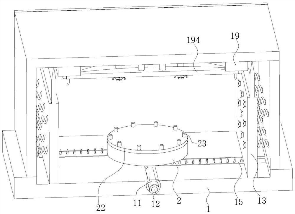
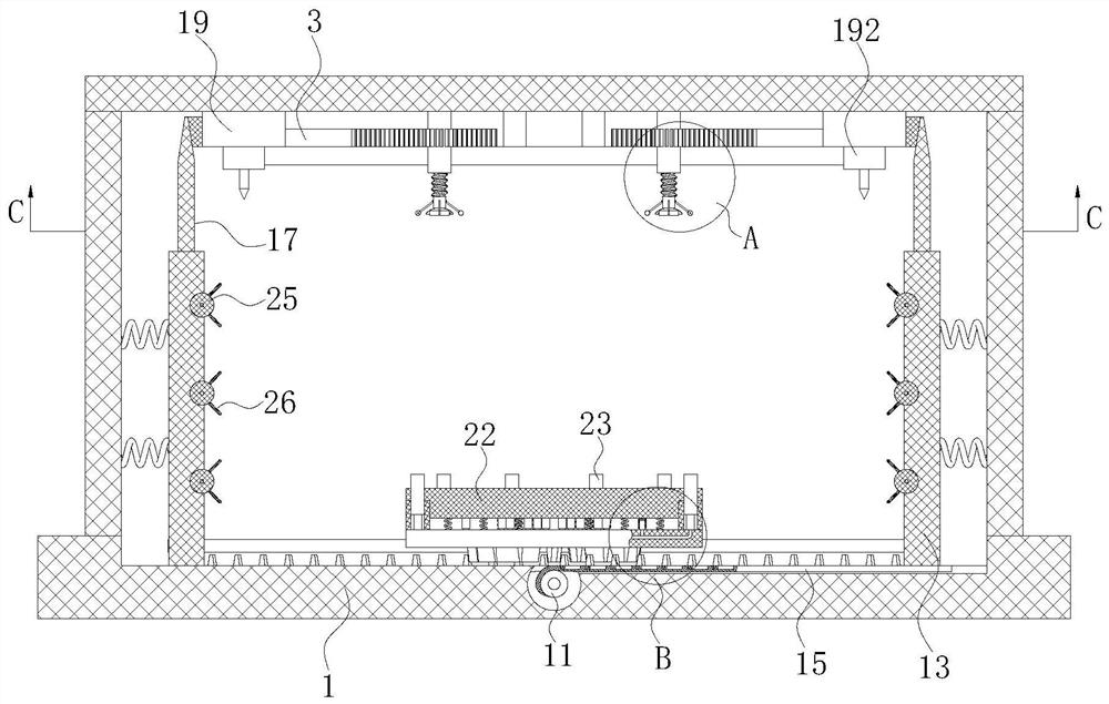
[0038] As an embodiment of the present invention, an annular groove is opened in the inner wall of the support plate 2, and the annular groove is designed around the support plate 2; a disc 22 is slidably connected to the inner wall of the annular groove through evenly arranged springs, and the circular groove is The discs 22 are closely fitted with the circular groove;

[0039] During work, owing to be connected with disc 22 by spring sliding in the supporting disc 2 inner wall, when needing to bind when the case cabinet that industrial design material uses is less, because case case is smaller, relatively lighter in weight relative to case case, here In the process, the supporting force of the cabinet by utilizing the disc 22 that is fixedly connected by the spring is greater, so that the cabinet can be promoted to move upwards. In this process, the height of the cabinet can be prevented from being insufficient, and the cabinet cannot be bound. During the binding process, th...


PUM


Abstract

The invention belongs to the technical field of industrial design material binding devices, and specifically relates to an industrial design material binding device; it includes a box body; a circular groove is opened in the inner wall of the bottom bottom plate of the box body; a circular groove is connected to the circular groove through a rotating shaft. Evenly arranged rotating rods, and the number of rotating rods is two and corresponding to each other; the opposite sides of the two rotating rods are fixedly connected to the outer surface of the box with motors; the drive shafts of the two motors are connected to the corresponding rotating rods The rods are fixedly connected; the box cavity is slidably connected with baffles in the inner walls of both sides of the box, and the baffles are fixedly connected with the inner walls of the box through springs; the present invention is mainly used to solve the problem of current industrial design materials In the process of cabinet binding, it is necessary to manually move the cabinet to a suitable position to bind the materials. At the same time, after one side of the cabinet is bound, the cabinet needs to be rotated to bind the other end of the cabinet. When changing the size of the cabinet, it is also necessary to continuously adjust the cabinet.

Description

technical field [0001] The invention belongs to the technical field of industrial design material binding devices, in particular to an industrial design material binding device. Background technique [0002] Industrial design, referred to as ID. It refers to the design of industrial products based on engineering, aesthetics and economics. Industrial design is divided into four categories: product design, environmental design, communication design, and design management; including modeling design, mechanical design, circuit design, clothing design, environmental planning, interior design, architectural design, UI design, graphic design, packaging design, advertising design, animation design, display design, website design, etc. Industrial design, also known as industrial product design, involves psychology, sociology, aesthetics, ergonomics, mechanical structure, photography, color science, etc. The industrial design brought about by industrial development and division of ...

Claims


Application Information

Patent Timeline
Patent Type & Authority Patents(China)
IPC IPC(8): B42B5/02
CPCB42B5/02
Inventor 林胜男李浩
Owner 美华建筑设计有限公司
Learn More