
Imaging method and imaging system for vehicle driving road condition and vehicle

A technology of vehicle driving and imaging method

Pending Publication Date: 2020-12-25
BOSCH AUTOMOTIVE PROD SUZHOU
View PDF0 Cites 0 Cited by
  • Summary
  • Abstract
  • Description
  • Claims
  • Application Information

AI Technical Summary

Problems solved by technology

[0004] In view of this, the present invention provides an imaging method, an imaging system, and a vehicle for vehicle driving conditions, thereby effectively solving or alleviating one or more of the above problems and other problems in the prior art

Method used


Image

  • Imaging method and imaging system for vehicle driving road condition and vehicle

Examples


Embodiment Construction

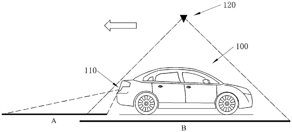
[0011] Please refer to figure 1 As shown, it provides an embodiment of the imaging system of the vehicle driving road conditions according to the present concept. The imaging system of the road condition of the vehicle includes a physical camera 110 for collecting image frames of the road condition, and a data control module for analyzing and processing the images collected by the physical camera so as to image the road condition of the vehicle. The imaging system i of the driving road condition of the vehicle includes a display screen to display the 3D road condition map of the driving area of ​​the vehicle, the virtual top view and the positioning of the vehicle acquired by the data control module.

[0012] Specifically, when an instruction is received to trigger the imaging method, or the imaging method is performed spontaneously, the following steps can be performed by the imaging system: First, S100 can be executed. During the driving process of the vehicle 100, a single ...


PUM


Abstract

The invention provides an imaging method and imaging system for a vehicle driving road condition and a vehicle. The imaging method for the vehicle driving road condition comprises the following steps:S100, acquiring a road condition image frame through a single entity camera on the vehicle; S200, splicing the road condition image frames to form a 3D road condition map of a vehicle driving area; S300, constructing a virtual camera arranged at the top of the vehicle, forming a virtual top view based on the 3D road condition map according to the visual angle of the virtual camera, and forming positioning of the vehicle in the 3D road condition map and the virtual top view; and S400, displaying the 3D road condition map and the virtual top view of the vehicle driving area and the positioningof the vehicle on a vehicle display screen. According to the method, an entity camera is used for collecting the road condition image frames; a control module is configured to execute the imaging method for the vehicle driving road condition; and the display screen is used for obtaining the 3D road condition map and the virtual top view of the vehicle driving area and positioning the vehicle basedon the imaging method for the vehicle driving road condition. According to the method, a driver is helped to observe the obstacle condition at the bottom of the vehicle through the single entity camera, the view monitoring around the vehicle is further perfected while the hardware cost is controlled, the existence of a view blind area is avoided, and the driving safety of the vehicle is improved.

Description

technical field [0001] The present application relates to the field of vehicles, and in particular to an imaging method and imaging system for driving road conditions of vehicles. Background technique [0002] Currently, vehicles are usually equipped with one or more cameras to monitor the environment around the vehicle, and display the images on the display screen in the cockpit to realize functions such as assisted driving or parking. Especially for reverse parking, because the driver's own vision is limited, he can only rely on the assistance of rearview mirrors and cameras to obtain the road conditions in the reverse path, so as to ensure the correct route and avoid obstacles. However, in the actual application process, safety problems may still occur due to the existence of blind spots in the field of vision. [0003] For example, on the one hand, for a vehicle with a rear-view camera, the driver cannot rely on the rear-view camera to observe the obstacle situation aro...

Claims


Application Information

Patent Timeline
IPC IPC(8): B60R1/00
CPCB60R1/00B60R2300/303B60R2300/607B60R2300/802
Inventor 莫博范叶峰
Owner BOSCH AUTOMOTIVE PROD SUZHOU
Learn More