Double-pump flow dividing and combining control system and control method thereof
A technology of a control system and a control method, which is applied in the field of dual-pump hydraulics, can solve problems such as the speed change of the actuator, and achieve the effect of improving smoothness and realizing high-speed operation.
- Summary
- Abstract
- Description
- Claims
- Application Information
AI Technical Summary
Problems solved by technology
Method used
Image
Examples
Embodiment 1
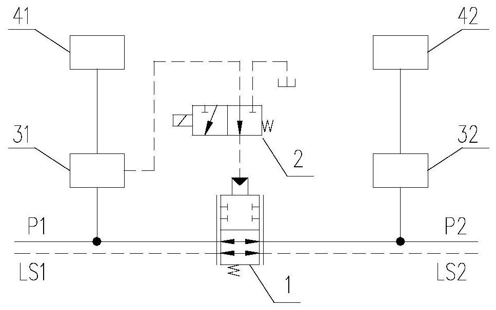
[0036] like figure 1 As shown, a dual-pump diversion and confluence control system includes a confluence valve 1, an electromagnetic reversing valve 2, a first actuator control valve 31, a second actuator control valve 32, a first actuator 41, and a second actuator 42. .
[0037]In this scheme, the first oil inlet P1 is connected to the outlet of the first hydraulic pump, the first feedback oil path LS1 is connected to the load feedback port of the first hydraulic pump, the second oil inlet P2 is connected to the outlet of the second hydraulic pump, and the second feedback oil path LS1 is connected to the load feedback port of the first hydraulic pump. The oil passage LS2 is connected to the load feedback port of the second hydraulic pump. The confluence valve 1 has 2 working positions (the lower position is the through position, and the upper position is the cut-off position), 1 control oil port, and more than 2 working oil ports. Road P1, the second oil inlet road P2, the ...
Embodiment 2
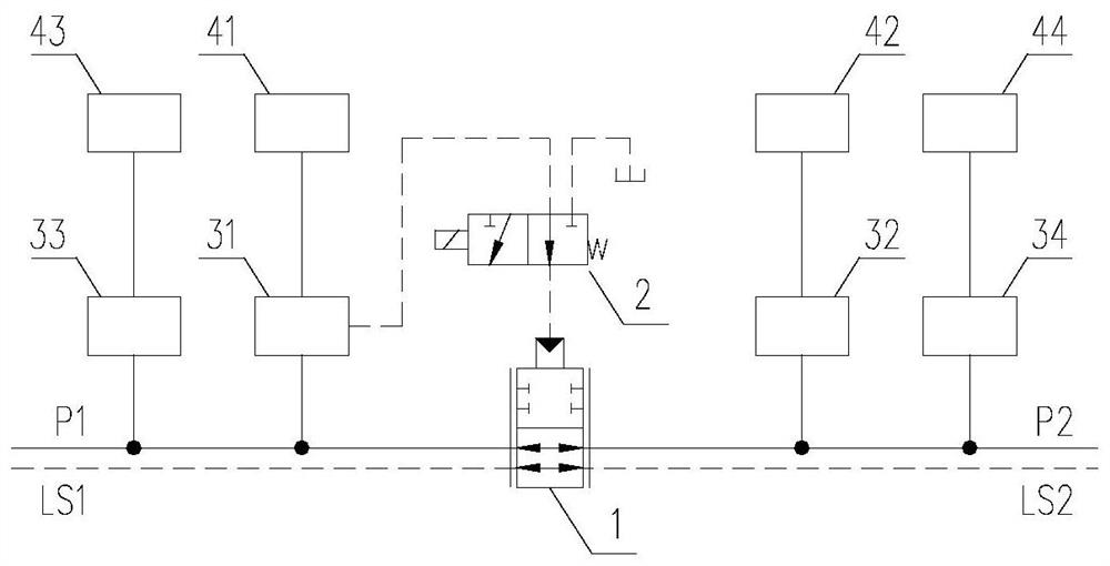
[0041] like figure 2 As shown, a dual-pump diversion and confluence control system includes a confluence valve 1, an electromagnetic reversing valve 2, a first actuator control valve 31, a second actuator control valve 32, a third actuator control valve 33, and a fourth actuator control valve. The mechanism controls the valve 34 , the first actuator 41 , the second actuator 42 , the third actuator 43 , and the fourth actuator 44 .
[0042] Operating any one of the second actuator 42 , the third actuator 43 , and the fourth actuator 44 alone can realize dual pumps to supply oil at the same time, which improves the operating efficiency of the actuator.
[0043] The electromagnetic reversing valve 2 can be controlled by a button on the joystick that can be automatically reset. When the first actuator 41 needs to reach the maximum speed of the double pump oil supply, it is only necessary to press and hold the control button to make the electromagnetic reversing valve 2 Power on,...
Embodiment 3
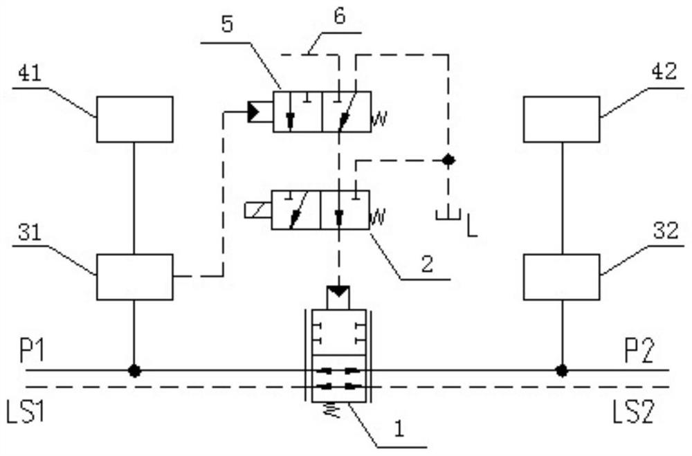
[0045] like image 3 As shown, on the basis of Embodiment 1, a hydraulic control reversing valve 5 is added, and the feedback pressure of the control valve of the first actuator 41 is used as the control pressure of the hydraulic control reversing valve 5, and the hydraulic control reversing valve 5 The second oil inlet port 6 is connected to a stable pilot oil source.
PUM
 Abstract
Description
Claims
Application Information
 - R&D
- Intellectual Property
- Life Sciences
- Materials
- Tech Scout
- Unparalleled Data Quality
- Higher Quality Content
- 60% Fewer Hallucinations
Browse by: Latest US Patents, China's latest patents, Technical Efficacy Thesaurus, Application Domain, Technology Topic, Popular Technical Reports.
© 2025 PatSnap. All rights reserved.Legal|Privacy policy|Modern Slavery Act Transparency Statement|Sitemap|About US| Contact US: help@patsnap.com


