Film evaporation type flame stabilizer and combustion chamber
A flame stabilizer, evaporative technology, applied in combustion chambers, continuous combustion chambers, combustion methods, etc., can solve the problems of lean fuel ignition and flame stabilization capability difficult to meet the working requirements of wide flight envelopes, and achieve improved ignition performance and Flame stabilization capability, increased gas phase fuel concentration, and the effect of widening operating range
- Summary
- Abstract
- Description
- Claims
- Application Information
AI Technical Summary
Problems solved by technology
Method used
Image

Examples
Embodiment 1
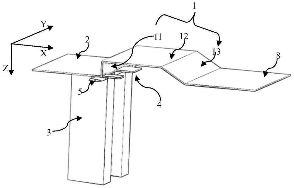
[0027] Embodiment 1: as figure 1 As shown, the direction of X in the figure is the axial direction described in this embodiment, which is also the front-to-back direction, and the direction in which the Z-axis extends in the figure is the radial direction described in this embodiment, which is also the direction from top to bottom , the direction in which the Y axis extends in the figure is the horizontal direction described in this embodiment, which is also the direction from left to right. The horizontal direction described in this embodiment is the direction parallel to the plane formed by the X-Y axis. The vertical direction of is the direction parallel to the plane formed by the Z-Y axis.
[0028] Such as figure 1 with figure 2 As shown, the thin film evaporative flame holder of the present invention includes a concave cavity flame holder 1 and a horizontally extending first distributor plate 2 arranged at the front end of the concave cavity flame holder 1, and the con...
Embodiment 2
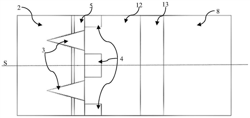
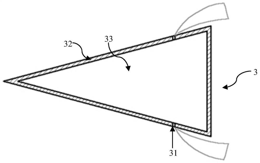
[0033] Embodiment 2: as Image 6 As shown, the thin-film evaporative flame stabilizer of embodiment 1 is applied in the rectangular combustion chamber, and the ignition nozzle 7 of the combustion chamber is opened on the main board 12, and the trailing edge of the liquid film covering plate 4 is preferably no more than the opening of the ignition nozzle 7 Location. The concave cavity flame stabilizer 1, the first splitter plate 2 and the second splitter plate 8 are affixed to the side wall surface of the rectangular combustion chamber 9 through both sides; The lower end surface of the plate flame stabilizer 3 is affixed to the lower wall of the rectangular combustion chamber 9, the support plate flame stabilizer 3 is a thin-walled hollow part, the outer shell 32 forms a triangular blunt body structure, and the ignition nozzle 7 is welded or mechanically fitted. The method is fixed on the upper wall surface of the rectangular combustion chamber 9, and passes through the main b...
PUM
| Property | Measurement | Unit |
|---|---|---|
| Length | aaaaa | aaaaa |
| Thickness | aaaaa | aaaaa |
| Length | aaaaa | aaaaa |
Abstract
Description
Claims
Application Information
 - R&D
- Intellectual Property
- Life Sciences
- Materials
- Tech Scout
- Unparalleled Data Quality
- Higher Quality Content
- 60% Fewer Hallucinations
Browse by: Latest US Patents, China's latest patents, Technical Efficacy Thesaurus, Application Domain, Technology Topic, Popular Technical Reports.
© 2025 PatSnap. All rights reserved.Legal|Privacy policy|Modern Slavery Act Transparency Statement|Sitemap|About US| Contact US: help@patsnap.com