Chemical fiber static electricity removing device

A static electricity removal device and technology of chemical fiber yarns, applied in the direction of static electricity, electrical components, transportation and packaging, etc., can solve problems such as insufficient protection measures, untidy chemical fiber yarns, and imperfect automatic control instruments, etc.

Pending Publication Date: 2020-12-25
滁州兴邦聚合彩纤有限公司
View PDF1 Cites 1 Cited by
  • Summary
  • Abstract
  • Description
  • Claims
  • Application Information

AI Technical Summary

Problems solved by technology

[0004] The main purpose of the present invention is to provide a static electricity removal device for chemical fiber, which can effectively solve the problems in the background technology that the protection measures are not perfect, the automatic control equipment is not perfect, and the collected chemical fiber is not neat enough.

Method used


Image

  • Chemical fiber static electricity removing device
  • Chemical fiber static electricity removing device
  • Chemical fiber static electricity removing device

Examples


Embodiment 1

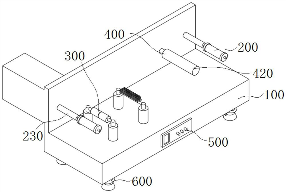
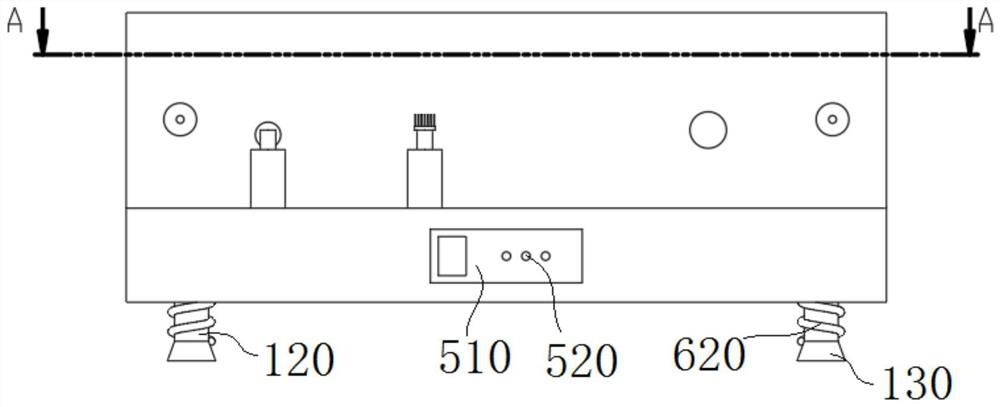
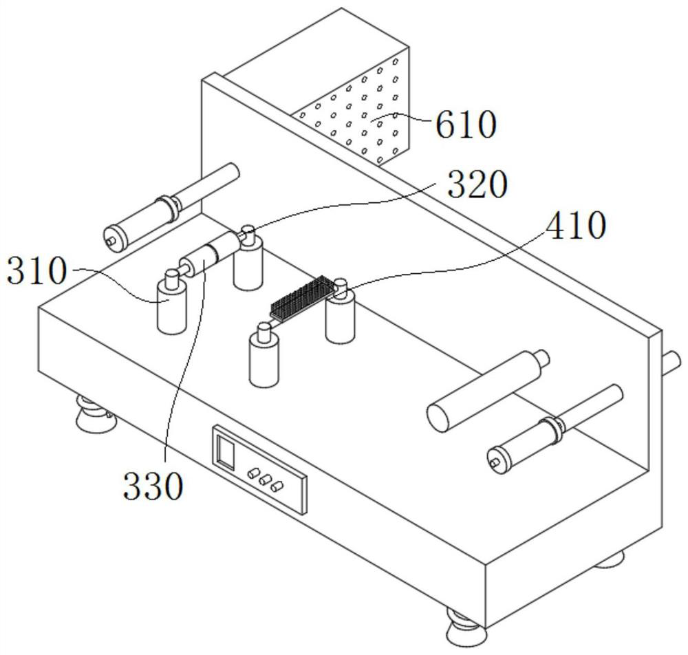
[0028] Please refer to figure 1 As shown in -4, the present invention is a chemical fiber thread static removal device, including a load-bearing structure 100, a transmission structure 200, a finishing structure 300, a processing structure 400, a control structure 500 and a protection structure 600, and the load-bearing structure 100 includes a workbench 110 and a support The column 120 and the lower surface of the workbench 110 are provided with several installation grooves, and the side surfaces of several support columns 120 are respectively connected with several installation grooves. One side surface is welded with the side surface of the workbench 110, the motor box 210 is a hollow structure, the motor 220 is installed inside the motor box 210, the side surface of the motor 220 is provided with a rotating groove, and the rotating shaft 230 is rotatably matched with the rotating groove, and the finishing structure 300 includes The connecting columns 310 and the connecting...

Embodiment 2

[0036] Please refer to figure 1 Shown in -4, the present invention is a kind of chemical fiber yarn removing static electricity device, and support column 120 and support foot 130 mainly play the purpose of supporting device, and wire transfer roller 250 rolls the chemical fiber yarn just produced, and wire take-up roller 240 passes through motor 220 Rotate to collect the processed chemical fiber yarn. When the chemical fiber yarn passes through the finishing roller 330, it will be tensioned therein. When the chemical fiber yarn passes through the static elimination roller 420, the leather set on it can eliminate static electricity. The control knob 520 mainly controls The speed of the motor 220 is used to control the speed of the take-up roller 240 and the like.


PUM


Abstract

The invention relates to a chemical fiber static electricity removal device, and belongs to the technical field of static electricity removal. The device comprises a bearing structure, a transmissionstructure, an arrangement structure, a processing structure, a control structure and a protection structure. The bearing structure comprises a workbench and supporting columns, a plurality of mountinggrooves are formed in the lower surface of the workbench, and the surfaces of one sides of the supporting columns are connected with the mounting grooves. The transmission structure comprises a motorbox, a motor, a rotating shaft and a fiber collecting roller, the surface of one side of the motor box is welded to the surface of one side of the workbench, the motor box is of a hollow structure, the motor is installed in the motor box, a rotating groove is formed in the surface of one side of the motor, and the rotating shaft is in rotating fit with the rotating groove. According to the chemical fiber static electricity removal device, the workbench is supported by the supporting columns and the supporting legs, chemical fibers which are just produced are wound by a fiber conveying roller,the treated chemical fibers are collected by the fiber collecting roller through rotation of the motor, and a finishing roller mainly plays a tensioning role.

Description

technical field [0001] The invention relates to the technical field of static electricity removal, in particular to a static electricity removal device for chemical fiber filaments. Background technique [0002] Chemical fiber yarn is made of natural polymer compound or artificially synthesized polymer compound as raw material. It is a fiber with textile properties obtained through the preparation of spinning dope, spinning and post-treatment. The chemical fiber yarn that has just been produced for a long time often carries A lot of static electricity, and the existence of static electricity is often not conducive to storage and transportation, so static electricity should be removed. [0003] The static electricity removal device in the prior art has shortcomings such as insufficient protection measures, imperfect automatic control instruments, and untidy collection of chemical fiber filaments. For this reason, we have proposed a static electricity removal device for chemic...

Claims


Application Information

Patent Timeline
Patent Type & Authority Applications(China)
IPC IPC(8): H05F3/00B65H59/10B65H54/44
CPCH05F3/00B65H54/44B65H59/10B65H2701/31
Inventor 徐建军胡庆文奚永新陈国平
Owner 滁州兴邦聚合彩纤有限公司
Why Eureka
Try Eureka