A kind of sweet potato starch filtration equipment
A filter equipment, sweet potato starch technology, applied in the direction of filtration separation, fixed filter element filter, separation method, etc., can solve the problems of troublesome operation, effort, waste, etc., and achieve the effect of convenient operation
- Summary
- Abstract
- Description
- Claims
- Application Information
AI Technical Summary
Problems solved by technology
Method used
Image

Examples
Embodiment 1
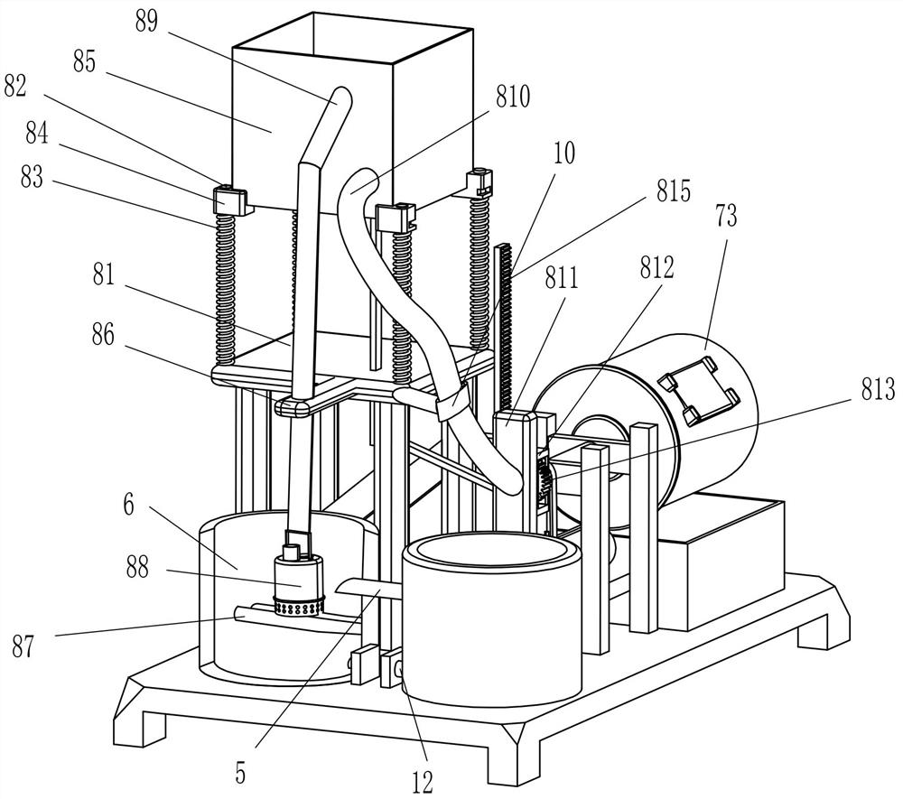
[0024] A sweet potato starch filtering equipment, such as Figure 1-Figure 4 As shown in the figure, it includes a starch filtering equipment, including a base 1, a collection frame 2, a first conduit 3, a sedimentation bucket 4, a second conduit 5, a reservoir 6, a filter mechanism 7 and a drive mechanism 8 , a collection frame 2 is fixed on the right side of the top of the base 1, a first conduit 3 is fixed in the middle of the front side of the left side of the collection frame 2, and the first conduit 3 communicates with the collection frame 2, and the top left front of the base 1 is fixed with a The sedimentation bucket 4, the lower part of the right side of the sedimentation bucket 4 is fixedly connected with the tail end of the first conduit 3, the first conduit 3 is communicated with the sedimentation bucket 4, and a reservoir 6 is fixedly connected to the left rear of the top of the base 1, and the reservoir 6 A second conduit 5 is fixedly connected between the upper ...
Embodiment 2
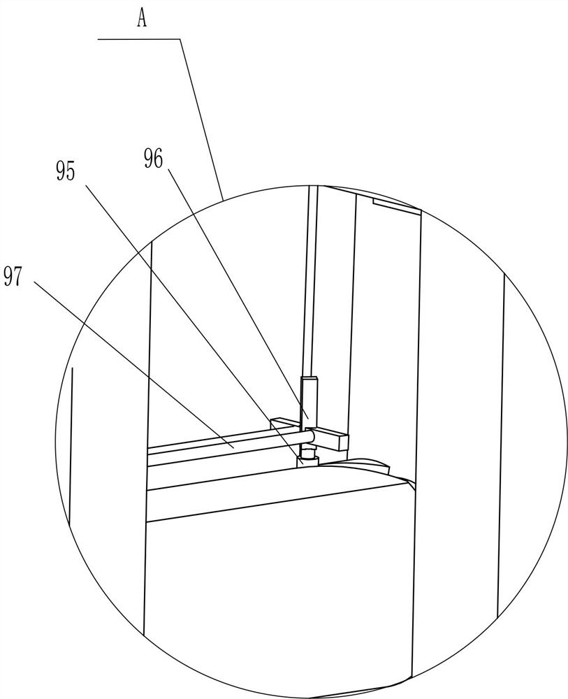
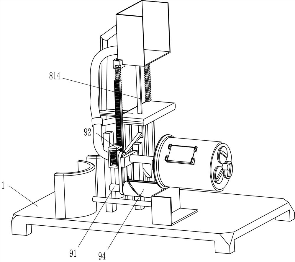
[0031] On the basis of Example 1, as figure 1 , image 3 , Figure 4 and Figure 5 As shown, it also includes a transmission mechanism 9. The transmission mechanism 9 includes a transmission rod 91, a transmission assembly 92, a slot column 94, a slider 95, a cross fixing frame 96, a second sliding rod 97 and an arc-shaped sliding block 98. The lower part of the right side of the fixing frame 81 is rotatably provided with a transmission rod 91 , a transmission assembly 92 is connected between the outer left peripheral direction of the porous hollow shaft 72 and the left peripheral direction of the transmission rod 91 , and a groove column is fixedly connected to the right peripheral direction of the transmission rod 91 94, a sliding block 95 is slidably arranged in the groove column 94, a cross fixing frame 96 is fixed on the top of the sliding block 95, and a second sliding rod 97 is symmetrically fixed on the right side of the cross fixing frame 96, and the second sliding ...
Embodiment 3
[0034] On the basis of Example 1 and Example 2, as figure 1 and figure 2 As shown, a fixing sleeve 10 is also included, and the fixing sleeve 10 is fixedly connected between the upper front side of the left side surface of the second fixing frame 81 and the circumferential direction of the middle part of the hose 810 .
[0035] It also includes an observation device 11. The observation device 11 includes a transparent glass 1101 and a third fixing block 1102. Two third fixing blocks 1102 are fixed symmetrically on the upper left and right sides of the outer front side of the cylinder 73, and four third fixing blocks 1102. A transparent glass 1101 is fixed between the inner sides of the three fixing blocks 1102 , and the transparent glass 1101 is embedded and fixed on the cylinder 73 .
[0036] When the water in the water collecting frame 85 flows into the porous hollow shaft 72 through the hose 810, the fixing sleeve 10 can fix the hose 810, so that the hose 810 can be preve...
PUM
 Abstract
Description
Claims
Application Information