Gas-liquid separator with double liquid level switches

A technology of gas-liquid separator and liquid level switch, which is applied in the direction of separation method, dispersed particle separation, machine/engine, etc., which can solve the problems of potential safety hazards, inability to observe the liquid level of the separator, unsafe and other problems

Pending Publication Date: 2020-12-29
BENGBU GAOKE ENERGY EQUIP
View PDF0 Cites 0 Cited by
  • Summary
  • Abstract
  • Description
  • Claims
  • Application Information

AI Technical Summary

Problems solved by technology

[0004] However, if the gas-liquid separator is not equipped with a liquid level gauge, there is still a greater risk of bringing the liquid into the next stage of the cylinder in the working condition with a lot of liquid phase
At this time, the drain valve is usually manually or automatically opened regularly to drain the liquid or oil. However, this draining method is based on the premise that the user has certain experience in the working conditions, otherwise it will have negative effects or safety hazards.
For example, because there is no liquid level gauge installed, it is impossible to observe the liquid level in the separator, and it cannot be discharged in time when the liquid level reaches the liquid discharge state, or it is frequently discharged when the liquid level does not reach the liquid discharge state, so It is a waste of resources and unsafe

Method used


Image

  • Gas-liquid separator with double liquid level switches

Examples


Embodiment Construction

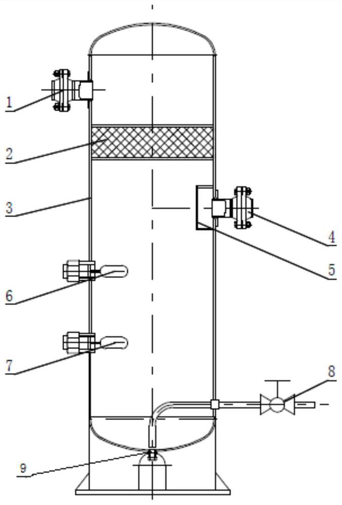
[0019] like figure 1 shown, figure 1 It is a schematic structural diagram of a double liquid level switch gas-liquid separator proposed by the present invention.

[0020] refer to figure 1 , The present invention proposes a double liquid level switch gas-liquid separator, including a separator cylinder 3 .

[0021] An air inlet is arranged in the middle of the separator cylinder 3, an inlet valve 4 is arranged at the inlet, and an inlet baffle 5 is arranged inside the separator cylinder 3 at the inlet.

[0022] An exhaust port is provided on the upper part of the separator cylinder 3, and an exhaust valve 1 is provided at the exhaust port.

[0023] A liquid discharge port is provided at the bottom of the separator cylinder 3, and a liquid discharge valve 8 is provided at the liquid discharge port. Specifically, the drain valve 8 is provided on the outer side of the separator cylinder 3, and the drain valve 8 is connected to the drain port through a pipeline.

[0024] A fi...


PUM


Abstract

According to the double-liquid-level-switch gas-liquid separator, a first liquid level switch and a second liquid level switch are arranged, and the detection liquid level of the first liquid level switch is higher than that of the second liquid level switch; the first liquid level switch and the second liquid level switch are electrically connected with the master controller, the master controller is electrically connected with the warning device for warning, and the master controller is electrically connected with the drain valve for draining liquid. When the liquid level of the gas-liquid separator rises to the detection position of the second liquid level switch, the main controller controls the warning device to give a liquid level warning according to a signal of the second liquid level switch and controls the liquid discharging valve to automatically discharge liquid. And when the liquid level of the gas-liquid separator rises to the detection position of the first liquid levelswitch, the main controller controls the warning device to carry out liquid level warning according to a signal of the first liquid level switch and controls to cut off a power supply of the compressor to stop the compressor. The working condition of the compressor can be better mastered, and the operation safety of the compressor can be guaranteed under the condition of unmanned monitoring.

Description

technical field [0001] The invention relates to the technical field of gas-liquid separation, in particular to a double-liquid level switch gas-liquid separator for a compressor. Background technique [0002] Usually compressors are used to transport gases, not liquids. During the operation of the compressor, even if a little liquid enters the compressor, the phenomenon of "liquid hammer" or "top cylinder" may occur, which may cause serious damage to the compressor, and even lead to a safety accident involving the destruction of the machine. Especially in the condition of compressing easily liquefied medium, a suitable gas-liquid separator must be used to prevent liquid from entering the compressor before the compressed medium enters the compressor cylinder, so as to ensure the safe operation of the compressor. [0003] In the field of compressor matching, the common gas-liquid separators mainly include three types: cyclone type, folded plate type and wire mesh type, and so...

Claims


Application Information

Patent Timeline
Patent Type & Authority Applications(China)
IPC IPC(8): B01D45/18F04B39/16
CPCB01D45/18F04B39/16
Inventor 王月华吕金钢徐芝信
Owner BENGBU GAOKE ENERGY EQUIP
Why Eureka
Try Eureka