
A kind of back drilling tool and preparation method thereof

A tool and back-drilling technology, applied in the field of back-drilling tools and its preparation, can solve problems such as poor thickness uniformity, difficult process control, and limited back-drilling ability, and achieve the effect of improving processing efficiency and processing accuracy

Active Publication Date: 2021-06-18
GUANGDONG DTECH TECH CO LTD
View PDF0 Cites 0 Cited by
  • Summary
  • Abstract
  • Description
  • Claims
  • Application Information

AI Technical Summary

Problems solved by technology

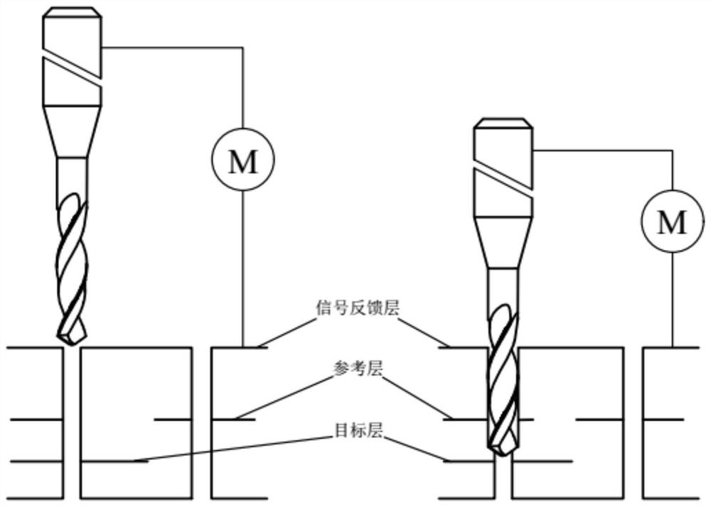
The disadvantage of method 1 is that the back-drilling depth of the holes processed by this back-drilling method is consistent, and the thickness of the board is uneven. Generally, the board is thinner around the board and thicker in the middle, so the copper remaining in the hole after back-drilling Poor length uniformity limits the improvement of back-drilling capability. The thicker the board, the worse the thickness uniformity and the greater the length of residual copper
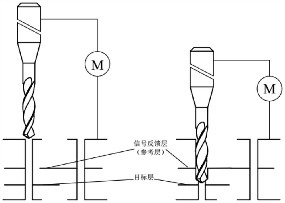
The disadvantage of method 2 is: the inner layer is used as the signal feedback layer for back drilling, which is excellent in controlling the copper length of the hole, and the plate thickness uniformity will no longer be an influencing factor for back drilling, but it has high requirements for other steps in the production process. The process control is difficult, and the diameter of back drilling is more than 0.3mm larger than that of the first drilling

Method used


Image

  • A kind of back drilling tool and preparation method thereof
  • A kind of back drilling tool and preparation method thereof
  • A kind of back drilling tool and preparation method thereof

Examples


Embodiment Construction

[0037] In order to enable those skilled in the art to better understand the technical solution of the present invention, the technical solution of the present invention will be further described below in conjunction with the accompanying drawings and through specific implementation methods.

[0038] In the description of the present invention, unless otherwise clearly specified and limited, the terms "connected", "connected" and "fixed" should be understood in a broad sense, for example, it can be a fixed connection, a detachable connection, or an integrated ; It can be a mechanical connection or an electrical connection; it can be a direct connection or an indirect connection through an intermediary, and it can be the internal communication of two components or the interaction relationship between two components. Those of ordinary skill in the art can understand the specific meanings of the above terms in the present invention in specific situations.

[0039] In the present i...


PUM

PropertyMeasurementUnit
lengthaaaaaaaaaa

Abstract

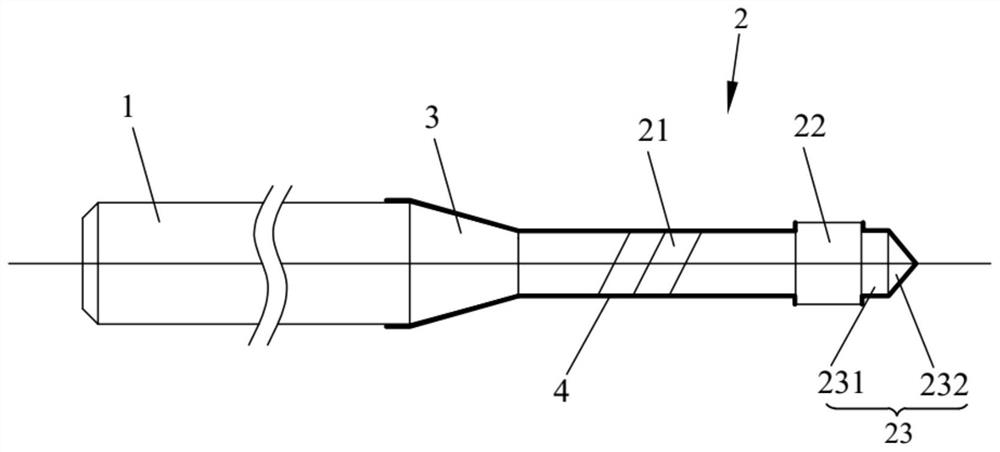
The invention relates to the technical field of circuit board processing, in particular to a back drilling tool and a preparation method thereof. The back drilling tool provided by the present invention comprises a handle and a blade, and the blade includes a blade body, a boss and a knife tip connected in sequence, and the blade body is connected to the handle; the maximum diameter of the blade tip and the diameter of the blade body are all less than the diameter of the boss; the blade tip The outer surface of the knife body is non-conductive, and the outer surface of the boss is conductive. During processing, the boss forms an electrical path with the inner layer of the workpiece, which plays a role in signal transmission, so that the hole depth can be precisely controlled. Through innovative tool structure design, get rid of the dependence of hole depth accuracy on workpiece thickness and process control, greatly improve processing efficiency and processing accuracy. The back-drilling tool preparation method provided by the present invention is used for processing the above-mentioned back-drilling tool, so that the back-drilling tool can accurately control the hole depth during back-drilling, get rid of the dependence of hole depth accuracy on workpiece thickness and process control, and greatly improve Processing efficiency and processing accuracy.

Description

technical field [0001] The invention relates to the technical field of circuit board processing, in particular to a back drilling tool and a preparation method thereof. Background technique [0002] The plated-through-hole (PTH) in the multilayer printed circuit board (Printed-Circuit-Board, referred to as PCB) plays the role of interconnecting the inner layer power layer and the ground layer. When the system enters the high-speed signal During transmission, the PTH hole will become the bottleneck and obstacle of signal integrity. It is like an excess "tail" (Stubs) in the transmission line, which acts as a notch filter. In the signal transmission line, two such When stubs are used, a section of oscillation will be formed, whether it is filtering or oscillation, it will cause damage to high-speed signal transmission and distort the signal. Back-drilling is to remove the part of copper (Stubs) that is not conducive to signal transmission in the PTH hole that has been electro...

Claims


Application Information

Patent Timeline
Patent Type & Authority Patents(China)
IPC IPC(8): B26F1/16B23P15/32
CPCB26F1/16B23P15/32
Inventor 郑鑫陈汉泉
Owner GUANGDONG DTECH TECH CO LTD
Learn More