A troweling device for the manufacture of cement manhole covers
A technology for manhole covers and cement, applied in the direction of manufacturing tools, ceramic molding machines, etc., can solve the problems of high labor intensity, inability to scrape cement mud, and reduce the quality of cement manhole covers, and achieve the effect of improving quality and improving troweling efficiency.
- Summary
- Abstract
- Description
- Claims
- Application Information
AI Technical Summary
Problems solved by technology
Method used
Image
Examples
Embodiment 1
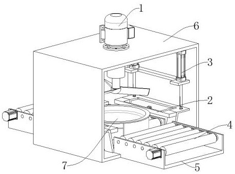
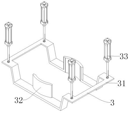
[0039] Such as figure 1 , image 3 , Figure 5 , Image 6 , Figure 7 , Figure 8 As shown, the lifting mechanism 3 includes a lifting frame 31, a support base 32, and a lifting cylinder 33. The fixed part of the lifting cylinder 33 is connected to the front and rear sides of the support frame 6 by bolts. The support seat 32 is connected to the middle position of the lifting frame 31 by welding, and the lifting frame 31 is driven by the telescopic part of the lifting cylinder 33 to lift, and the support seat 32 from the lifting frame 31 is lifted to drive the mold 7 to lift and smooth Conveying mechanism 4 comprises the first conveying roller 41, conveying motor 42, pulley 43, belt 44, the second conveying roller 45, the 3rd conveying roller 46, the first conveying roller 41, the 2nd conveying roller 45 and the 3rd conveying roller 46 are all connected to the inner side of the base 5 through bearings, the third conveying roller 46 is located on one side of the second conv...
Embodiment 2
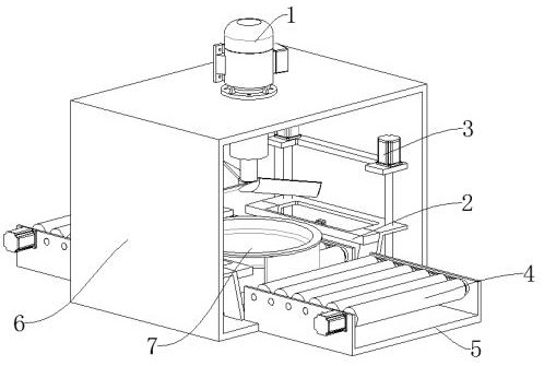
[0042] Such as figure 2 , Figure 4 As shown, the difference between Embodiment 2 and Embodiment 1 is that the lifting mechanism 3 includes a lifting frame 31, a support base 32, a lifting motor 313, and a lead screw 314. The lifting motor 313 is connected to the front and rear sides of the support frame 6 by bolts. The upper and lower ends of the bar 314 are connected to the front and rear sides of the support frame 6 through bearings. The leading screw 314 is located below the lifting motor 313. The front and rear ends of the lifting frame 31 are connected to the outside of the leading screw 314 by threads. In the middle position of the lifting frame 31, the rotating part of the lifting motor 313 is used to drive the screw 314 to rotate, and the rotation of the screw 314 drives the lifting frame 31 to go up and down, and the support seat 32 from the lifting frame 31 is lifted to drive the mold 7. Carry out lifting and troweling.
PUM
 Abstract
Description
Claims
Application Information
 - R&D
- Intellectual Property
- Life Sciences
- Materials
- Tech Scout
- Unparalleled Data Quality
- Higher Quality Content
- 60% Fewer Hallucinations
Browse by: Latest US Patents, China's latest patents, Technical Efficacy Thesaurus, Application Domain, Technology Topic, Popular Technical Reports.
© 2025 PatSnap. All rights reserved.Legal|Privacy policy|Modern Slavery Act Transparency Statement|Sitemap|About US| Contact US: help@patsnap.com


