Hollow forming machine and method convenient for taking out plastic bottles for cosmetics

A technology for plastic bottles and cosmetics, applied to hollow objects, applications, household appliances, etc., can solve the problems of inconvenient removal of plastic bottles, complicated mold opening of molding machines, complicated processing steps, etc., and achieve the effect of reducing labor costs

Inactive Publication Date: 2020-12-29
吴敏
View PDF5 Cites 2 Cited by
  • Summary
  • Abstract
  • Description
  • Claims
  • Application Information

AI Technical Summary

Problems solved by technology

[0002] The plastic injection blow molding machine can place the tubular plastic parison obtained by extrusion or injection molding of thermoplastic resin in the split mold while it is hot (or heated to a softened state), and immediately pass it into the parison after closing the mold. Compress air to inflate the plastic parison and cling to the inner wall of the mold. After cooling and demoulding, various hollow products can be obtained. The existing plastic bottles need to heat the semi-finished products and place them in the molding machine manually. The cavity is blown by the wind to form a plastic bottle. The processing steps are complicated, and the mold opening of the molding machine is complicated, and it is not easy to take out the plastic bottle. Therefore, we have proposed a hollow molding machine and method for cosmetics that are easy to take out the plastic bottle.

Method used


Image

  • Hollow forming machine and method convenient for taking out plastic bottles for cosmetics
  • Hollow forming machine and method convenient for taking out plastic bottles for cosmetics
  • Hollow forming machine and method convenient for taking out plastic bottles for cosmetics

Examples


Embodiment Construction

[0027] The following will clearly and completely describe the technical solutions in the embodiments of the present invention with reference to the accompanying drawings in the embodiments of the present invention. Obviously, the described embodiments are only some, not all, embodiments of the present invention. Based on the embodiments of the present invention, all other embodiments obtained by persons of ordinary skill in the art without making creative efforts belong to the protection scope of the present invention.

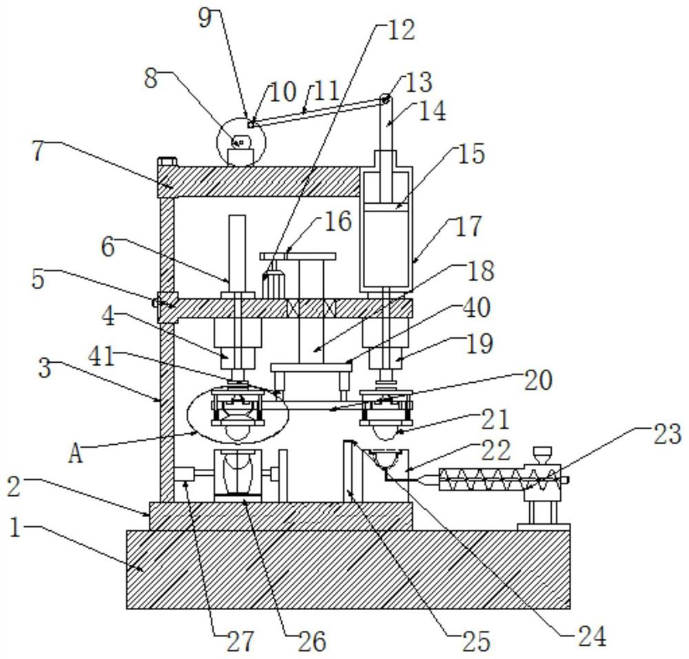
[0028] see figure 1 , the present invention provides a technical solution: a hollow molding machine for cosmetics that is convenient for taking out plastic bottles, comprising a frame 1 and a base 2, the left side of the upper end surface of the frame 1 is provided with a base 2, and the left side of the upper end surface of the base 2 is provided with a Fixed rod 3, the middle part of fixed rod 3 is movably connected with support plate 5, the upper end of fix...


PUM


Abstract

The invention belongs to the technical field of hollow forming machines and discloses a hollow forming machine convenient for taking out plastic bottles for cosmetics. The machine comprises a frame and a base, the left side of the upper end face of the frame is provided with the base, the left side of the upper end face of the base is provided with a fixing rod, the middle of the fixing rod is movably connected with a support plate, and a fixing plate is fixedly connected to the upper end of the fixing rod. A supporting rotating rod penetrates through the right side of the end face of the supporting plate from top to bottom, a rotating rod is arranged at the lower end of the supporting rotating rod, hydraulic rods are arranged on the left side and the right side of the lower end face of the rotating rod, and supporting rods are fixedly connected to the lower end faces of the hydraulic rods. A cylinder is arranged at the right end face of the fixing plate, and the lower end face of thecylinder is fixedly arranged at the right side of the upper end face of the supporting plate. A driving motor is arranged at the left side of the upper end face of the fixing plate. A disc is fixedlyconnected to the front end face of the motor shaft of the driving motor. A fixing shaft is arranged at the outer ring of the front end of the disc, and a connecting rod is movably connected to the outer ring of the fixing shaft. The device has the advantages that the structure is simple, the operation is convenient, the mechanical operation replaces the manual operation, the labor cost is effectively reduced, and the product qualification rate is improved.

Description

technical field [0001] The invention relates to the technical field of hollow molding machines, in particular to a hollow molding machine and a method for taking out plastic bottles for cosmetics. Background technique [0002] The plastic injection blow molding machine can place the tubular plastic parison obtained by extrusion or injection molding of thermoplastic resin in the split mold while it is hot (or heated to a softened state), and immediately pass it into the parison after closing the mold. Compress air to inflate the plastic parison and cling to the inner wall of the mold. After cooling and demoulding, various hollow products can be obtained. The existing plastic bottles need to heat the semi-finished products and place them in the molding machine manually. The cavity is blown by the wind to form a plastic bottle. The processing steps are complicated, and the mold opening of the molding machine is complicated, and it is not easy to take out the plastic bottle. The...

Claims


Application Information

Patent Timeline
Patent Type & Authority Applications(China)
IPC IPC(8): B29C49/70B29C49/06B29C49/28B29C49/42B29C49/50B29C49/56B29L22/00
CPCB29C49/70B29C49/06B29C49/28B29C49/4252B29C49/50B29C49/56B29L2022/00B29C2049/023
Inventor 吴敏
Owner 吴敏
Why Eureka
Try Eureka