Pipe wall flattening equipment for large pipe recovery
A pipe and pipe wall technology, which is applied in the field of pipe wall flattening equipment for large-scale pipe recycling, can solve the problems of single machine function, easy to cause danger, and inability to push materials, so as to speed up the movement speed, improve work efficiency, and save manpower. Effect
- Summary
- Abstract
- Description
- Claims
- Application Information
AI Technical Summary
Problems solved by technology
Method used
Image

Examples
Embodiment 1
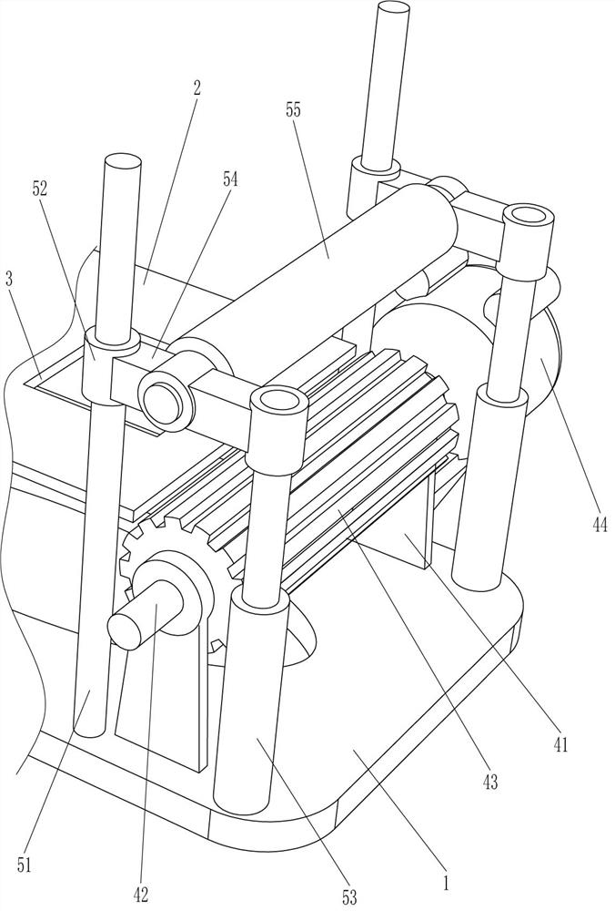
[0047] A pipe wall flattening equipment for large-scale pipe recycling, such as figure 1 As shown, it includes a bottom plate 1, an operating table 2, a flattening mechanism 4 and a pressing mechanism 5. The left side of the bottom plate 1 is connected with the operating table 2, the right side of the operating table 2 is opened with a through hole 3, and the right side of the bottom plate 1 is connected with a pressing machine. The flattening mechanism 4 is connected with a pressing mechanism 5 on the right side of the bottom plate 1, and the pressing mechanism 5 is located on the outside of the flattening mechanism 4.
[0048] When people need to flatten the pipes, the pipes are first placed on the console 2 so that the right side of the pipes fits the parts of the flattening mechanism 4, and the parts of the pressing mechanism 5 are controlled to move downward, so that the parts of the pressing mechanism 5 The components flatten the right side of the pipe, and then start th...
Embodiment 2
[0050] On the basis of Example 1, such as figure 2 As shown, the flattening mechanism 4 includes a fixed plate 41, a rotating shaft 42, a pressure roller 43 and a reduction motor 44. The right side of the bottom plate 1 is connected to the fixed plate 41 on both sides, and the top of the fixed plate 41 is connected to the rotating shaft 42 in a rotational manner. , the outside of rotating shaft 42 is provided with pressure roller 43, bottom plate 1 right rear side is connected with reduction motor 44, reduction motor 44 is positioned at fixed plate 41 rear side, and the output shaft of reduction motor 44 is connected with rotating shaft 42 rear ends.
[0051] When people need to flatten the pipe, they first place the pipe on the console 2 so that the right side of the pipe fits the pressure roller 43, and with the cooperation of the pressing mechanism 5, the right side of the pipe is flattened, and then the deceleration is started The motor 44 and the output shaft of the redu...
Embodiment 3
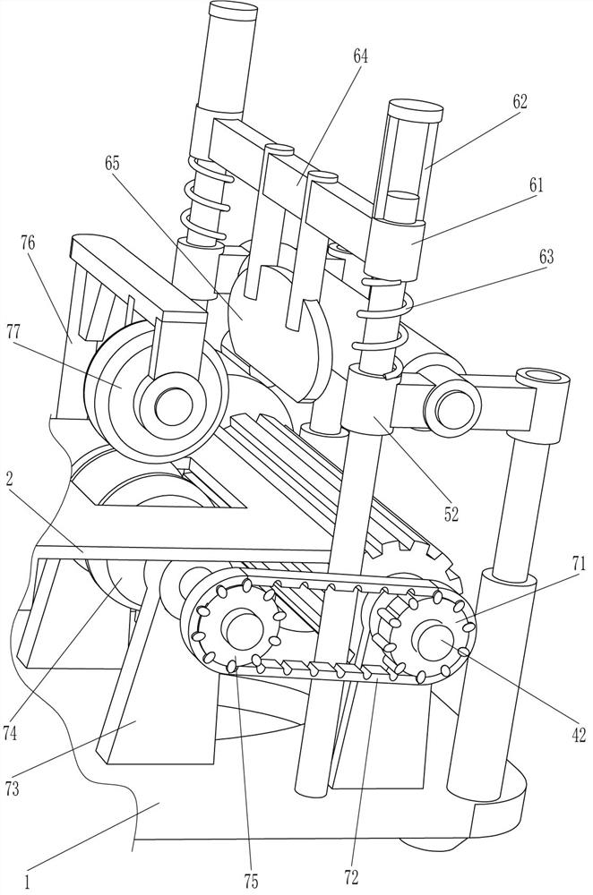
[0055] On the basis of Example 2, such as Figure 3-4 As shown, a side opening mechanism 6 is also included, and the side opening mechanism 6 includes a sliding sleeve 61, a limit tube 62, a spring 63, a mounting frame 64 and an arc-shaped contact plate 65, and the upper part of the vertical bar 51 is slidably connected with a sliding sleeve 61, a spring 63 is connected between the bottom of the sliding sleeve 61 and the top of the guide sleeve 52, and the spring 63 is set on the outside of the vertical bar 51, and the top of the sliding sleeve 61 is connected with a limit tube 62, and the limit tube 62 and the vertical bar 51 slide Connection, the upper part of the limit tube 62 is attached to the vertical bar 51, the mounting frame 64 is connected between the sliding sleeves 61, and the middle bottom of the mounting frame 64 is connected with an arc-shaped contact plate 65.
[0056] When the guide sleeve 52 moves downward, because the material of the spring 63 is hard, the spr...
PUM
 Abstract
Description
Claims
Application Information
 - R&D Engineer
- R&D Manager
- IP Professional
- Industry Leading Data Capabilities
- Powerful AI technology
- Patent DNA Extraction
Browse by: Latest US Patents, China's latest patents, Technical Efficacy Thesaurus, Application Domain, Technology Topic.
© 2024 PatSnap. All rights reserved.Legal|Privacy policy|Modern Slavery Act Transparency Statement|Sitemap