Outlet can-supporting device of pop-top can cleaning and drying machine

A technology for dryers and cans, which is applied in the direction of conveyors, conveyor objects, transportation and packaging, etc. It can solve problems such as prone to dumping, reduce the damage rate of tanks, prevent tanks from dumping, and ensure quality.

Active Publication Date: 2020-12-29
济南联合制罐有限公司
View PDF6 Cites 1 Cited by
  • Summary
  • Abstract
  • Description
  • Claims
  • Application Information

AI Technical Summary

Problems solved by technology

[0004] The invention provides a can support device at the outlet of a can cleaning and drying machine, which is used to solve the problem that the can body is prone to tipping when it moves on the transmission mechanism, and achieve the beneficial effects of preventing the can body from tipping over and reducing the damage rate of the can body

Method used


Image

  • Outlet can-supporting device of pop-top can cleaning and drying machine
  • Outlet can-supporting device of pop-top can cleaning and drying machine
  • Outlet can-supporting device of pop-top can cleaning and drying machine

Examples


Embodiment 1

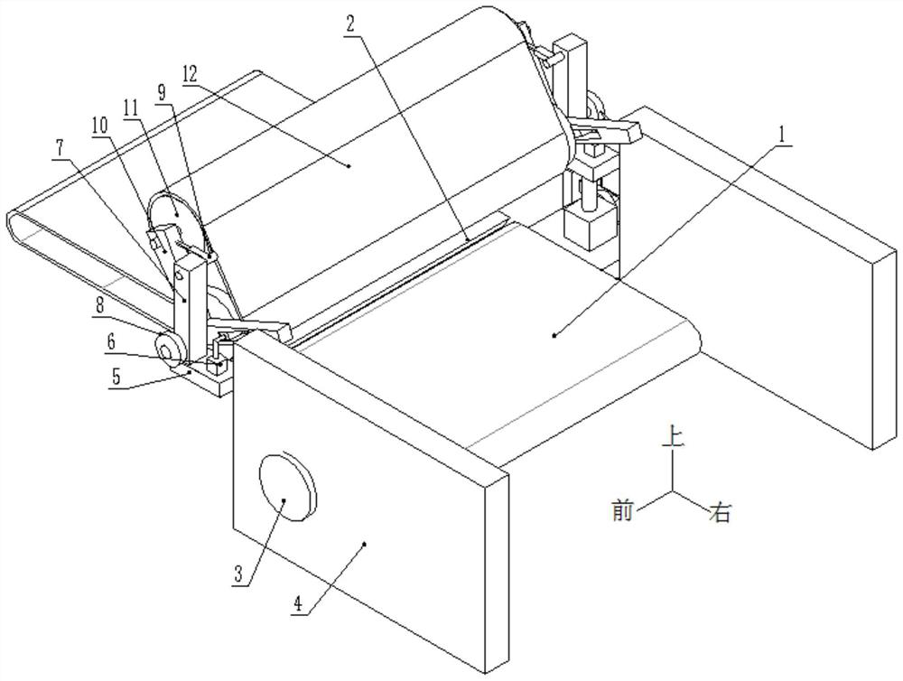
[0035] A device for supporting cans at the outlet of a can cleaning and drying machine, such as figure 1 As shown, it includes a transmission mechanism 1, a transition plate 2 and a power assembly 3, wherein a transmission mechanism 1 is located in the washing and drying machine 4, and the two sides of the transmission mechanism 1 are respectively equipped with a centralizing mechanism, and the centralizing mechanism includes installation Plate 5, first electric push rod 6, vertical plate 7, driving wheel 8, first telescopic rod 9, connecting frame 10, driven wheel 11 and conveyor belt 12. The righting mechanism is used for righting the pop cans that pass through the transition plate 2.

[0036] Such as figure 1 As shown, one side of the transmission mechanism 1 is provided with a mounting plate 5, the mounting plate 5 is provided with a first electric push rod 6 and a riser 7, and the drive wheel 8 and the first telescopic rod 9 are installed on the riser 7. A connecting fr...

Embodiment 2

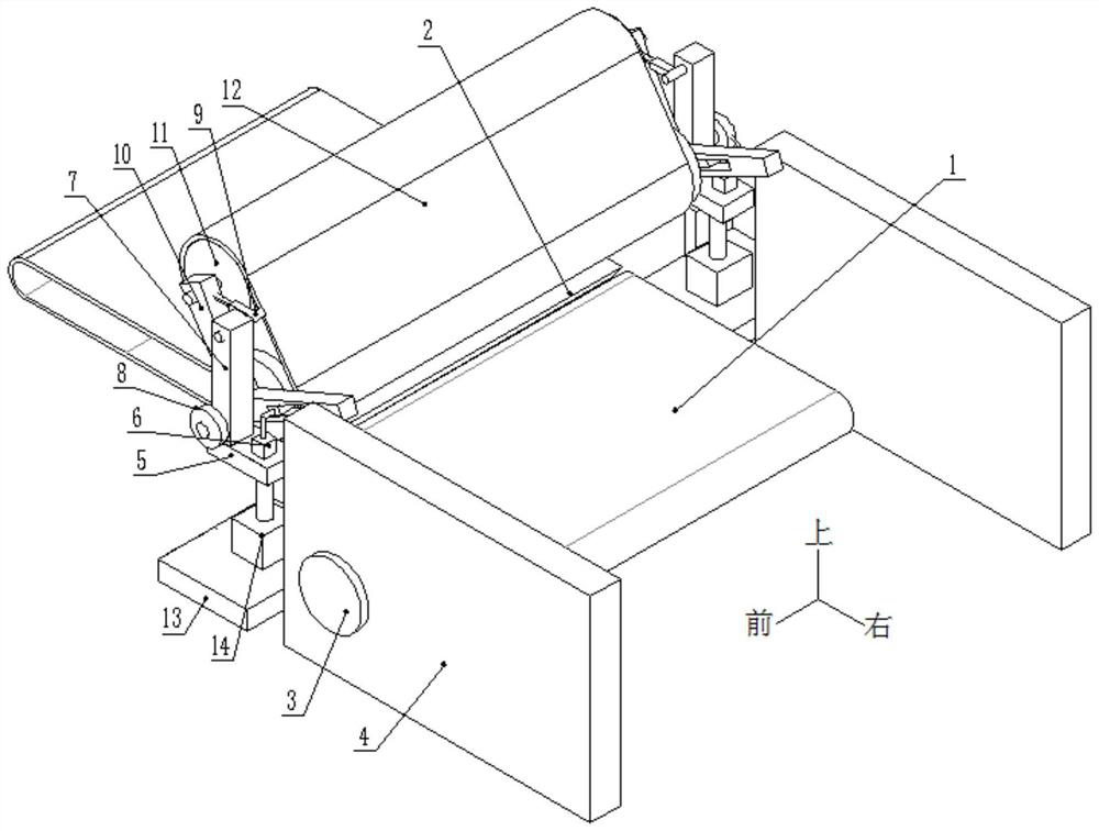
[0042] On the basis of Example 1, such as figure 2 As shown, one side of the transmission structure 1 is provided with a horizontal plate 13, and the horizontal plate 13 is provided with a second electric push rod 14 connected to the mounting plate 5, and the movable end of the second electric push rod 14 moves to drive; the mounting plate 5 It is movably connected with the cleaning and drying machine 4 frame, and one side of the mounting plate 5 is provided with a bump, and one side of the cleaning and drying machine 4 frame is provided with a groove matched with the bump, which guides the movement of the mounting plate 5.

[0043] The specifications of cans are different. For cans of different heights, the position of the righting device needs to be adjusted in time to achieve the original righting effect. Before use, the staff starts the second electric push rod 14, the movable end of the second electric push rod 14 moves to make the installation plate 5 move along the was...

Embodiment 3

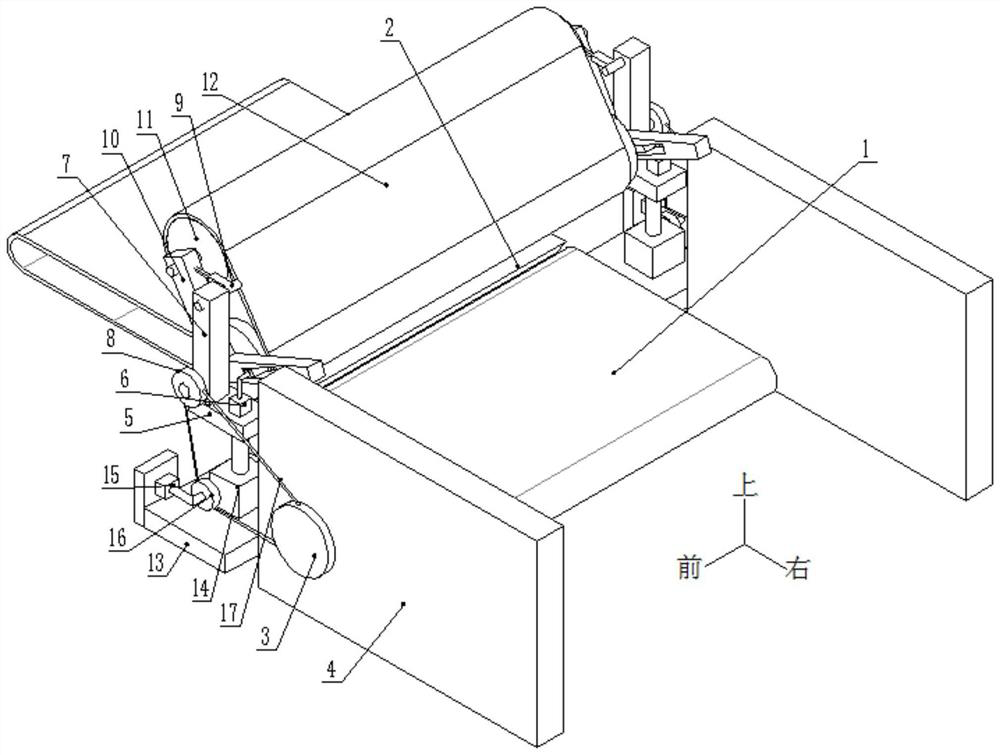
[0045] On the basis of Example 2, such as Figure 3-Figure 6 As shown, the power source adopts the power assembly on the cleaning and drying machine 4; the side of the mounting plate 5 is provided with a lockable second telescopic rod 15, and the second telescopic rod 15 is provided with a connecting wheel 16. The driving wheel 8 includes two wheels symmetrically distributed around the vertical plate 7 , and a matching chain 17 is arranged between the connecting wheel 16 and the power assembly and the outer driving wheel 8 .

[0046] The driving wheel 8 and the connecting wheel 16 are provided with annular limiting plates; the driving wheel 8, the connecting wheel 16 and the power assembly are on the same level.

[0047] Such as Figure 9 As shown, the second telescopic rod 15 includes a fixed sleeve 151, a movable rod 152 and a locking assembly, the fixed sleeve 151 is provided with a movable rod 152 moving along it, and the fixed sleeve 151 is provided with a fixed movable ...


PUM


Abstract

The invention provides an outlet can-supporting device of a pop-top can cleaning and drying machine. The device comprises a conveying mechanism, a transition plate and a power assembly, wherein the conveying mechanism is located in the cleaning and drying machine, and the two sides of the conveying mechanism are each provided with a righting mechanism. Each righting mechanism comprises a mountingplate, a first electric push rod, a vertical plate, a driving wheel, a first telescopic rod, a connecting frame, a driven wheel and a conveying belt, wherein the mounting plate is arranged on one sideof the conveying mechanism, the first electric push rod and the vertical plate are arranged on the mounting plate, the driving wheel and the first telescopic rod are mounted on the vertical plate, the connecting frame is mounted between the driving wheel and the vertical plate, one end of the connecting frame is movably connected with the movable end of the first electric push rod, the driven wheel is arranged at the other end of the connecting frame and connected with the driving wheel through the conveying belt, and the driven wheel is connected with the movable end of the first telescopicrod.

Description

technical field [0001] The invention belongs to the technical field of pop can manufacturing, in particular to a can support device at the outlet of a pop can cleaning and drying machine. Background technique [0002] During the production process of the can body, it has to go through processes such as punching, crimping, glue injection, glue removal, drying and riveting ring. The track where the riveting tab operation is located. And when a row of can body blanks is pushed forward by a horizontal forward force to move forward on the track, when the front can body blanks pass through the transition plate, due to the gap between the transition plate and the transmission structure, it is easy to make individual tank bodies The billet dumping phenomenon affects the subsequent can body embryo transportation, and even blocks the entrance of the processing equipment, resulting in the shutdown of the entire production line; it also causes damage to the can body itself, affecting t...

Claims


Application Information

Patent Timeline
Patent Type & Authority Applications(China)
IPC IPC(8): B65G47/52B65G47/22B65G23/04
CPCB65G47/52B65G47/22B65G23/04B65G2201/0252
Inventor 高培宪
Owner 济南联合制罐有限公司
Why Eureka
Try Eureka