
Backwashing valve

A technology of backwashing and valves, which is applied in the direction of valve details, multi-way valves, valve devices, etc., can solve the problems of large amount of backwashing valves, high manufacturing costs, complex structures, etc., and achieve improved utilization and low manufacturing costs , cost reduction effect

Pending Publication Date: 2020-12-29
HENAN UNIV OF SCI & TECH
View PDF2 Cites 0 Cited by
  • Summary
  • Abstract
  • Description
  • Claims
  • Application Information

AI Technical Summary

Problems solved by technology

The backwash valve of this technology has a large volume and a relatively complicated structure, because in actual production, the backwash valve is often used in a large amount and the manufacturing cost is high, so it increases the economic burden of domestic agricultural irrigation and industrial production users, and is not suitable for industrial production in my country. Save water resources in agricultural production

Method used


Image

  • Backwashing valve
  • Backwashing valve

Examples


Embodiment 1

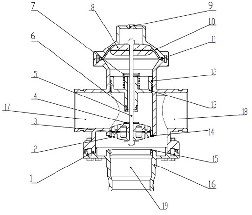
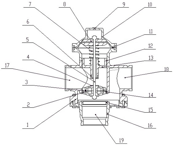
[0024] The water inlet 17 is connected to the water inlet pipe, one outlet 18 is connected to the water outlet pipe and the filter, the outlet pipe is provided with a ball valve as a control switch, and the lower flushing port 19 is connected to the inlet of the sewage well. High pressure is injected into the cavity, and the high pressure drives the diaphragm 11 and the sealing chuck 8 to move downward and compresses the spring 7, and the sealing chuck 8 drives the connecting rod 5 to squeeze the valve plug 2 so that the valve plug 2 moves downward and is tightly combined with the lower valve seat 16 , cut off the flushing port 19 of the lower valve body 16, and the drain port 18 of the upper valve body 1 is normally open at this time. The port 9 is emptied to reduce the pressure of the control chamber, the spring 7 returns to the initial state, the connecting rod 5 is driven upward by pulling the sealing chuck 8 and the diaphragm 11, and the valve plug 2 is driven by the conne...

Embodiment 2

[0026] The water inlet 17 is connected to the water inlet pipe, and the three outlets 18 are respectively connected to three outlet pipes and filters. Each outlet pipe is equipped with a ball valve as a switch, and the bottom flushing port 19 is connected to the sewage well inlet. Hydraulic control is performed in the filtering mode. The valve port 9 is pressurized, the control chamber injects high pressure, the high pressure pushes the diaphragm 11 and the sealing chuck 8 to move downward and compresses the spring 7, and the sealing chuck 8 squeezes the connecting rod 5 to drive the valve plug 2 so that the valve plug 2 and the lower The valve seat 16 is tightly combined to block the flushing port 19 of the lower valve body 16. At this time, the drain port 18 of the upper valve body 1 is normally open. When there are many impurities accumulated on the filter layer, the resistance of the incoming water passing through the filter layer is relatively large. The hydraulic control ...


PUM


Abstract

The invention provides a backwashing valve. The backwashing valve comprises an upper valve body, a lower valve body, a diaphragm leaf, a connecting rod and a valve cover on the upper side of the uppervalve body. A press plate is arranged in the upper valve body; a water inlet and a plurality of water discharging outlets are formed in the upper valve body; the water inlet and the water dischargingoutlets are uniformly distributed in the periphery of the upper valve body; a washing opening is formed in the lower valve body; the connecting rod penetrates through the upper valve body and the diaphragm leaf; and the diaphragm leaf is arranged at the upper end of the connecting rod and between the valve cover and the upper valve body. The connecting rod is connected with the diaphragm leaf through a sealing chuck which is arranged in the valve cover; a valve plug is arranged at the lower end of the connecting rod; the upper valve body is divided by the valve plug into a water inlet cavityand a water outlet cavity; a spring is arranged between the press plate and the sealing chuck; and the intensity of pressure is controlled by a hydraulic control valve port which is arranged at the top end of the valve cover, so that the diaphragm leaf and the sealing chuck are driven. The structure is simple; the reliability is high; it can be ensured that the backwashing valve stably runs for along time under the condition without maintenance; the manufacturing cost is low; and the cost for modern agricultural and industrial production is further reduced.

Description

technical field [0001] The invention relates to the fields of water filtration in modern agricultural drip irrigation technology and circulating water filtration treatment in industrial production, in particular to a reverse flushing valve. Background technique [0002] Backwash valves are widely used in modern agricultural water filtration and circulating water filtration in industrial production. The hydraulic control valve dedicated to the fully automatic backwashing filtration system is driven by the pressure of the pipeline system and can be switched automatically to realize automatic backwashing of the filter. Its high reliability can ensure long-term stable operation without maintenance, it can smoothly change the flow direction of water, close the water inlet when the backwash port is opened, and vice versa, and avoid filter overflow or clean water and waste water mix. [0003] In the prior art, the backwash valve is applied to an automatic backwash filtration syst...

Claims


Application Information

Patent Timeline
Patent Type & Authority Applications(China)
IPC IPC(8): F16K11/044F16K27/02F16K31/126B01D35/02B01D35/16
CPCF16K11/044F16K31/1262F16K27/0263B01D35/02B01D35/16
Inventor 张晓洋张彦斌贺少旭徐中海
Owner HENAN UNIV OF SCI & TECH
Learn More