Specially-shaped mixing holes for adjusting outlet temperature distribution of combustion chamber

A technology of outlet temperature and blending hole, applied in the direction of combustion chamber, continuous combustion chamber, combustion method, etc., can solve the problem of unreasonable outlet temperature distribution of combustion chamber, ablation of turbine guide/moving blade, and limited flow distribution of blending gas and other problems to achieve the effect of improving the quality of the outlet temperature distribution, improving the outlet temperature distribution, and improving the outlet temperature distribution.

Active Publication Date: 2020-12-29
NANJING UNIV OF AERONAUTICS & ASTRONAUTICS
View PDF14 Cites 5 Cited by
  • Summary
  • Abstract
  • Description
  • Claims
  • Application Information

AI Technical Summary

Problems solved by technology

In the high-temperature rise / low-emission combustion chamber, the flow distribution of the mixed gas is limited, and the penetration depth of the conventional circular hole jet is not enough, and the mixing is not sufficient, resulting in an unreasonable distribution of the temperature at the outlet of the combustion chamber, which will lead to repeated discharges on a certain radius of the turbine. Sustained high temperature resulting in turbine guide / bucket ablation

Method used


Image

  • Specially-shaped mixing holes for adjusting outlet temperature distribution of combustion chamber
  • Specially-shaped mixing holes for adjusting outlet temperature distribution of combustion chamber
  • Specially-shaped mixing holes for adjusting outlet temperature distribution of combustion chamber

Examples


Embodiment Construction

[0030] In order to make the purpose and effect of the present invention clearer, the present invention will be further described in detail below with reference to the accompanying drawings. It should be pointed out that the specific working process described here is only used to explain the present invention, not to limit the present invention.

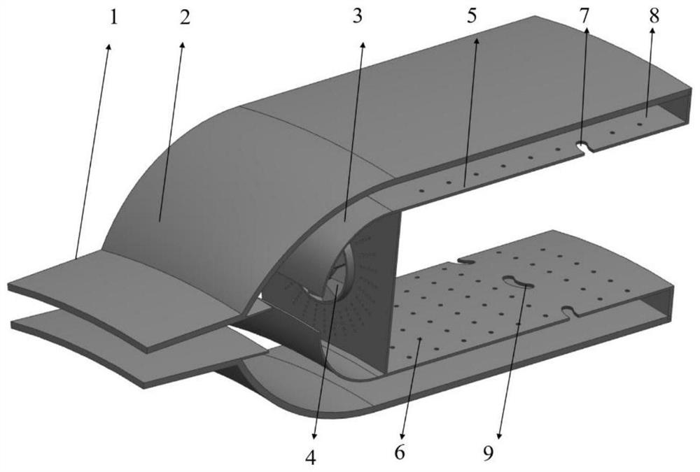
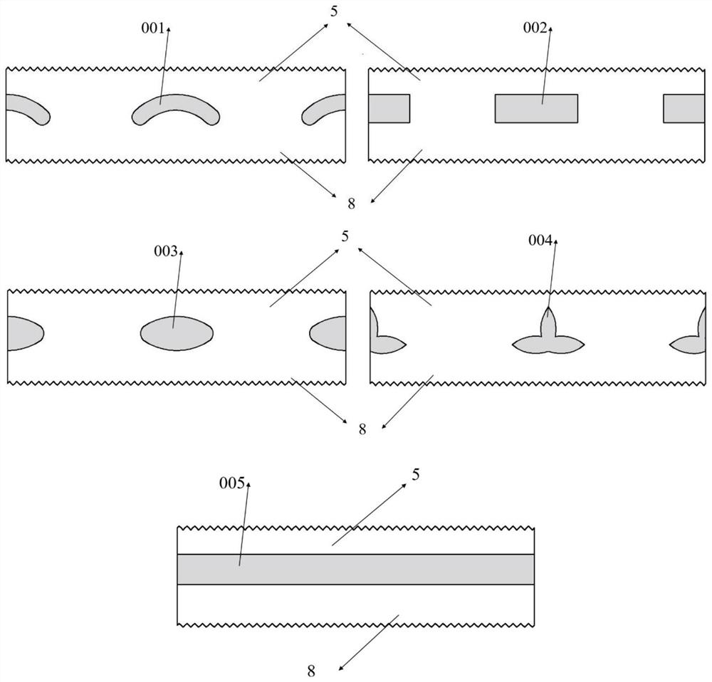
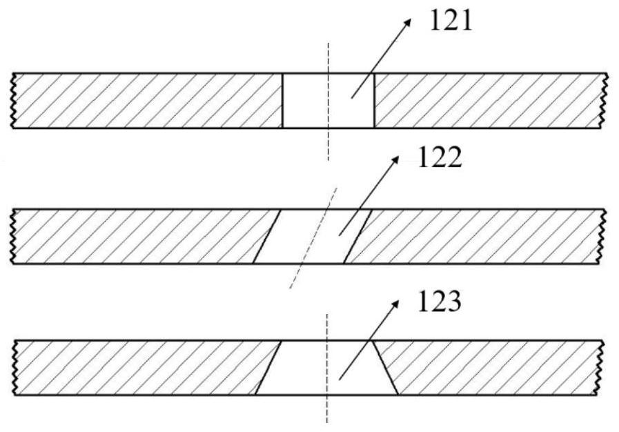
[0031] Such as figure 1 Shown is a schematic view of the structure of the combustion chamber with the special-shaped mixing hole for adjusting the outlet temperature distribution of the combustion chamber according to the present invention. The structure of the flame tube, the head of the flame tube is equipped with a multi-stage cyclone, and there are head cooling holes. The wall surface of the flame tube is distributed with wall film cooling holes 6 and special-shaped mixing holes. Evenly distributed in the direction. In the present invention, the special-shaped mixing hole arranged on the outer ring wall of the flame tube is set as...


PUM


Abstract

The invention discloses specially-shaped mixing holes for adjusting outlet temperature distribution of a combustion chamber, and belongs to the field of combustion of gas turbines. The specially-shaped mixing holes are formed in the inner ring wall surface and the outer ring wall surface of a flame tube of the combustion chamber correspondingly; the specially-shaped mixing holes divide the wall surface of the flame tube into a flame tube front section and a flame tube back section; the specially-shaped mixing holes are evenly distributed in the circumferential direction of the wall surface ofthe flame tube to form mixing jet flows evenly distributed in the circumferential direction, the penetration depth of the mixing jet flows is increased, the contact area of mixing cold air and high-temperature main stream gas is increased, the mixing effect is improved, and the outlet temperature distribution quality of the combustion chamber is improved; the effect of adjusting outlet temperaturedistribution of the combustion chamber is achieved by changing the jet flow penetration depths, the jet flow circumferential expansion angles and the jet flow directions of the mixing holes; and outlet temperature distribution of the combustion chamber is adjusted, so that the temperature quality of an inlet of a turbine is improved, the service life of the turbine is prolonged, and the heat-proof design difficulty of the turbine is reduced.

Description

technical field [0001] The invention belongs to the field of gas turbine combustion, and relates to a heterogeneous mixing hole for adjusting the outlet temperature distribution of a combustion chamber, in particular to a heterogeneous mixing hole structure for adjusting the temperature distribution of the combustion chamber outlet. Background technique [0002] The gas turbine combustor is one of the core components of the gas turbine. The current development trends of the combustor are as follows: first, in order to reduce pollution emissions, the combustor is developed towards low pollution; second, in order to improve the thrust-to-weight ratio of the gas turbine, the combustor is developed towards high temperature and high pressure ratio. The high temperature rise / low pollution emission requirements of the combustion chamber greatly increase the demand for air intake at the head of the combustion chamber, so the flow area of ​​the swirler is increased and the main combu...

Claims


Application Information

Patent Timeline
IPC IPC(8): F23R3/38
CPCF23R3/38
Inventor 张萍颜应文李伟刘云鹏李井华田泽民
Owner NANJING UNIV OF AERONAUTICS & ASTRONAUTICS
Why Eureka
Try Eureka