Rolling bearing fault feature extraction method based on PCHIP-LCD
A PCHIP-LCD, rolling bearing technology, applied in the field of mechanical fault diagnosis, can solve problems such as distortion, decomposition of component waveform burrs, etc., to achieve the effect of improving accuracy, smoothing the envelope fitting curve, and improving the accuracy of envelope fitting
- Summary
- Abstract
- Description
- Claims
- Application Information
AI Technical Summary
Problems solved by technology
Method used
Image
Examples
Embodiment 1
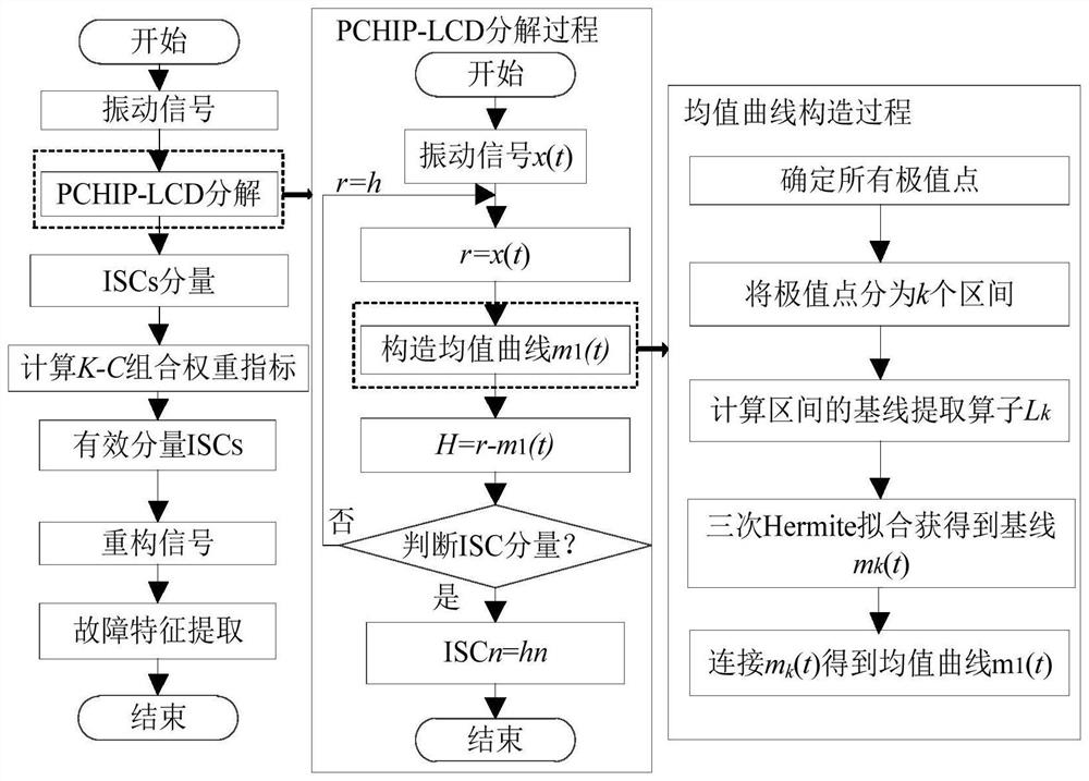
[0057] Example 1: The example uses bearing data from Case Western Reserve University, which is obtained through a bench test at a constant rotational speed. Such as figure 1 As shown, a rolling bearing fault feature extraction method based on PCHIP-LCD, the rolling bearing fault diagnosis method, the specific steps are:
[0058] Step1: Use the PCHIP-LCD method to decompose the vibration signal x(t) into several intrinsic scale components ISC 1 ,ISC 2 ,...,ISC m .
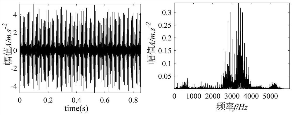
[0059] Step1.1: Collect the vibration signal r=x(t) of the rolling bearing, and the time-domain waveform diagram and frequency-domain diagram of the vibration signal r=x(t), such as image 3 shown.
[0060] Step1.2: Use the PCHIP method to construct the mean curve m 1 (t).
[0061] In the step Step1.2, the mean curve m 1 The construction steps of (t) are as follows:
[0062] Step1.2.1: Determine all extreme points of the signal x(t) (τ k ,X k ).
[0063] Step1.2.2: Divide extreme points into k intervals....
Embodiment 2
[0095] Example 2: The example uses bearing data from Case Western Reserve University, which is obtained through a bench test at a constant rotational speed. Such as figure 1 As shown, a rolling bearing fault feature extraction method based on PCHIP-LCD, the rolling bearing fault diagnosis method, the specific steps are:
[0096] Take the fault vibration signal data of the inner ring of the rolling bearing driving end for verification;
[0097] Step1: Use the PCHIP-LCD method to decompose the vibration signal x(t) into several intrinsic scale components ISC 1 ,ISC 2 ,...,ISC m .
[0098] Step1.1: Collect the vibration signal r=x(t) of the rolling bearing, and the time-domain waveform diagram and frequency-domain diagram of the vibration signal r=x(t) are as follows Figure 6 shown.
[0099] Step1.2: Use the PCHIP method to construct the mean curve m 1 (t).
[0100] In the step Step1.2, the mean curve m 1 The construction steps of (t) are as follows:
[0101]Step1.2.1:...
Embodiment 3
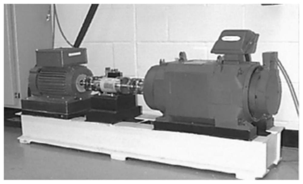
[0134] Embodiment 3: The platform used in Embodiment 3 is a NASA bearing life cycle experimental platform, a schematic diagram, as Figure 9 shown. In this paper, the NASA data length is 20480 points, the sampling frequency is 20kHz, the sampling point is 16384, the driving motor speed is 2000r / min, the radial load is 6000 pounds, and a total of 984 sets of data are collected.
[0135] Such as figure 1 As shown, a rolling bearing fault feature extraction method based on PCHIP-LCD, the rolling bearing fault diagnosis method, the specific steps are:
[0136] Take the fault vibration signal data of the outer ring of the rolling bearing driving end for verification;
[0137] Step1: Use the PCHIP-LCD method to decompose the vibration signal x(t) into several intrinsic scale components ISC 1 ,ISC 2 ,...,ISC m .
[0138] Step1.1: Collect the vibration signal r=x(t) of the rolling bearing, and the time-domain waveform diagram and frequency-domain diagram of the vibration signal ...
PUM
 Abstract
Description
Claims
Application Information
 - R&D
- Intellectual Property
- Life Sciences
- Materials
- Tech Scout
- Unparalleled Data Quality
- Higher Quality Content
- 60% Fewer Hallucinations
Browse by: Latest US Patents, China's latest patents, Technical Efficacy Thesaurus, Application Domain, Technology Topic, Popular Technical Reports.
© 2025 PatSnap. All rights reserved.Legal|Privacy policy|Modern Slavery Act Transparency Statement|Sitemap|About US| Contact US: help@patsnap.com


