
Power supply self-switching device and method

A technology of self-switching and power supply, which is applied in the direction of circuit devices, DC network circuit devices, and parallel operation of DC power supplies. It can solve the problems of increasing the cost of the whole machine, increasing power conversion, and obvious ripples, so as to reduce the overall cost of use. Effect of reducing efficiency loss and reducing voltage drop

Pending Publication Date: 2020-12-29
FUJIAN CENTM INFORMATION
View PDF0 Cites 0 Cited by
  • Summary
  • Abstract
  • Description
  • Claims
  • Application Information

AI Technical Summary

Problems solved by technology

When the product selects a lower voltage level as the power input, in the application mode of high power consumption, the loss of the wire is large or the cost of the wire is high, and the output cost of the front-end power supply jumps more obviously; when the product selects a higher voltage level as the power input , although it can reduce the wire loss and wire cost in the whole scene, but the power conversion is added inside the product, there is a certain degree of efficiency loss, and the duty cycle is high, and the ripple is more obvious
In addition, when the products designed with this scheme are used for secondary integration, because of the fixed voltage input, it is impossible to flexibly select the power input according to the usage scenario. machine cost

Method used


Image

  • Power supply self-switching device and method
  • Power supply self-switching device and method
  • Power supply self-switching device and method

Examples


Embodiment Construction

[0027] In order to enable those skilled in the art to better understand the technical solutions in this specification, the technical solutions in the embodiments of this specification will be clearly and completely described below in conjunction with the drawings in the embodiments of this specification. Obviously, the described implementation Examples are only some of the embodiments of the present application, but not all of them. Based on the embodiments of this specification, all other embodiments obtained by those skilled in the art without creative efforts shall fall within the scope of protection of the present application.

[0028] General idea of ​​the present invention is as follows:

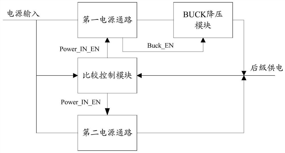
[0029] The present invention designs a power supply self-switching scheme using the characteristics of the BUCK chip. Using logic design, the power supply voltage is converted through the BUCK chip by default, and then the optimal power supply path is selected through the comparison re...


PUM


Abstract

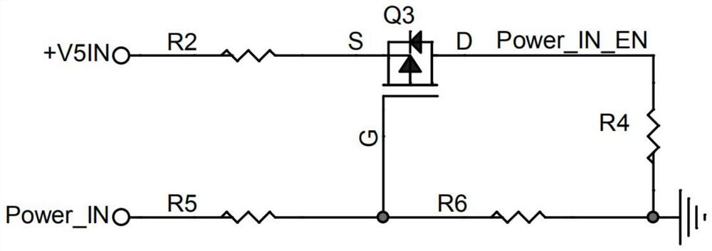
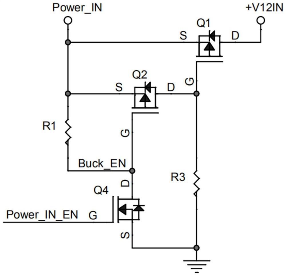
The invention discloses a power supply self-switching device which comprises a first power supply access, a second power supply access, a BUCK voltage reduction module and a comparison control module,the access control end of the comparison control module controls the first power supply access to be switched on by default, when the voltage of the power supply after voltage division is greater than the voltage of a post-stage power supply input end, the first power supply access is kept switched on, the BUCK voltage reduction module is enabled, and the power supply is connected with the post-stage power supply input end through the BUCK voltage reduction module; when the voltage of the power supply after voltage division is smaller than the voltage of the post-stage power supply input end,the access control end of the comparison control module enables the second power supply access to be connected, the BUCK voltage reduction module does not work, and the power supply is directly connected with the post-stage power supply input end through the second power supply access. According to the power supply self-switching device provided by the invention, low-voltage power supply can be directly adopted when a product use scene only has a low-power-consumption application, and high voltage is used as power supply input as required when the product use scene needs to cover a high-power-consumption application.

Description

technical field [0001] The invention relates to the field of power supply switching, in particular to a power supply self-switching device and method. Background technique [0002] The power consumption of some products varies greatly in different application modes, but the existing circuit design generally uses a fixed input voltage method for motherboard design. When the product selects a lower voltage level as the power input, in the application mode of high power consumption, the loss of the wire is large or the cost of the wire is high, and the output cost of the front-end power supply jumps more obviously; when the product selects a higher voltage level as the power input , although it can reduce the wire loss and wire cost in the whole scene, but the power conversion is added inside the product, there is a certain degree of efficiency loss, and the duty cycle is high, and the ripple is more obvious. In addition, when the products designed with this scheme are used fo...

Claims


Application Information

Patent Timeline
Patent Type & Authority Applications(China)
IPC IPC(8): H02J1/10H03K17/687
CPCH02J1/109H03K17/687
Inventor 陈培德张登峰朱明霞
Owner FUJIAN CENTM INFORMATION
Learn More