
Reactive power compensation device and control method with switching tube based on CAN bus

A CAN bus and compensation device technology, which is applied to the reactive power compensation device with switch tube and its control field, can solve the problems of inaccurate sampling signal, poor compensation effect, inability to meet the requirements of power factor, etc.

Active Publication Date: 2016-04-27
NANJING APAITEK TECH
View PDF5 Cites 0 Cited by
  • Summary
  • Abstract
  • Description
  • Claims
  • Application Information

AI Technical Summary

Problems solved by technology

Combined with its control method, it can effectively avoid the current signal attenuation in the prior art, which leads to inaccurate sampling signals, poor compensation effect and failure to meet the requirements of the national grid for power factor.

Method used


Image

  • Reactive power compensation device and control method with switching tube based on CAN bus

Examples


Embodiment Construction

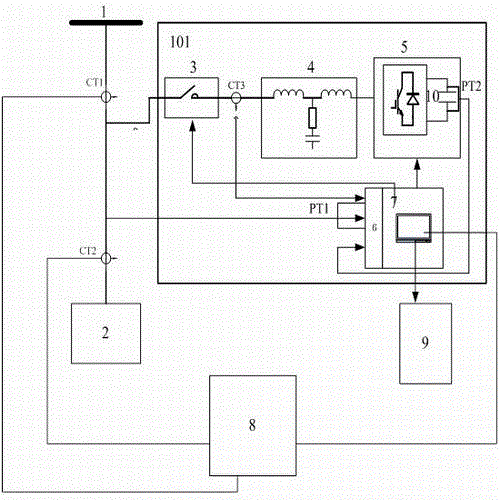
[0015] Such as figure 1 As shown, a reactive power compensation device with switching tubes based on CAN bus includes more than one electrical control box 101, each electrical control box includes an AC bus 1, and the AC bus 1 passes through the electrical The first current transformer CT1 and the second current transformer CT2 outside the control box 101 are then electrically connected to the reactive load 2, and the AC bus 1 is also connected to one end of the incoming line contactor 3 inside the electrical control box 101 Phase electrical connection, the conductor at the other end of the incoming line contactor 3 passes through the third current transformer CT3 inside the electrical control box 101 and then is electrically connected with the input end of the grid-connected filter 4 inside the electrical control box 101, The output end of the grid-connected filter 4 is electrically connected to the IGBT switch tube group 5 inside the electrical control box 101, and the gate ...


PUM


Abstract

The invention relates to a CAN (controller area network) bus-based reactive power compensation device provided with switching tubes, and a control method of the device. The CAN-based reactive power compensation device comprises more than one electrical control cabinet, wherein each electrical control cabinet comprises an alternating current (AC) bus; the AC buses sequentially penetrate through first current transformers and second current transformers which are arranged outside the electrical control cabinets, and are then electrically connected with a reactive load; the AC buses are also electrically connected with the ends of incoming line contactors arranged in the electrical control cabinets; conductors arranged at the other ends of the incoming line contactors penetrate through third current transformers arranged in the electrical control cabinets and are then electrically connected with input ends of grid connection filters arranged in the electrical control cabinets; output ends of the grid connection filters are electrically connected with insulated gate bipolar translator (IGBT) switching tube groups arranged in the electrical control cabinets; the defects that in the prior art, the sampling signals are not accurate, the compensation effect is poor, the requirement of the state grid corporation of China on the power factor cannot be reached due to the attenuation of current signals can be effectively avoided by the CAN-based reactive power compensation device combined with the control method of the device.

Description

technical field [0001] The invention belongs to the technical field of reactive power compensation, and in particular relates to a reactive power compensation device with a switching tube based on a CAN bus and a control method thereof. Background technique [0002] With the continuous improvement of the State Grid's requirements for power quality, the State Grid is gradually increasing the punishment for enterprises whose power factors do not meet the standards. Therefore, the conventional reactive power compensation device adopts CT series connection and PT parallel connection method to calculate the reactive power of the load in each compensation device. After multiple CTs are connected in series, the current signal attenuates, resulting in inaccurate sampling signals and poor compensation effect Meet the requirements of the national grid for power factor. Contents of the invention [0003] The object of the present invention provides a kind of reactive power compensat...

Claims


Application Information

Patent Timeline
Patent Type & Authority Patents(China)
IPC IPC(8): H02J3/18H02J13/00
CPCY02E40/30Y02E40/70Y04S10/22
Inventor 万里强李刚仇志凌张东芮国强温小林张明
Owner NANJING APAITEK TECH
Learn More