
Tail gas treatment device

A technology for exhaust gas treatment and air outlet cavity, which is used in gas treatment, combined device, climate change adaptation, etc. area, and the effect of reducing cross-flow and backflow phenomena

Active Publication Date: 2021-01-01
厦门艾涂仕环保设备有限公司
View PDF18 Cites 1 Cited by
  • Summary
  • Abstract
  • Description
  • Claims
  • Application Information

AI Technical Summary

Problems solved by technology

[0004] The invention provides an exhaust gas treatment device, aiming to solve the problems of low atomization density and insufficient spraying of the spray box

Method used


Image

  • Tail gas treatment device
  • Tail gas treatment device
  • Tail gas treatment device

Examples


Embodiment Construction

[0030]In order to make the objectives, technical solutions and advantages of the embodiments of the present invention clearer, the technical solutions in the embodiments of the present invention will be described clearly and completely in conjunction with the accompanying drawings in the embodiments of the present invention. Obviously, the described embodiments It is a part of the embodiments of the present invention, not all the embodiments. Based on the embodiments of the present invention, all other embodiments obtained by those of ordinary skill in the art without creative work fall within the protection scope of the present invention. Therefore, the following detailed description of the embodiments of the present invention provided in the accompanying drawings is not intended to limit the scope of the claimed invention, but merely represents selected embodiments of the present invention. Based on the embodiments of the present invention, all other embodiments obtained by those ...


PUM


Abstract

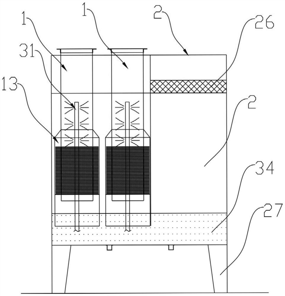
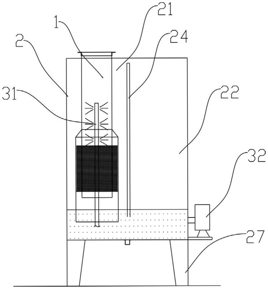
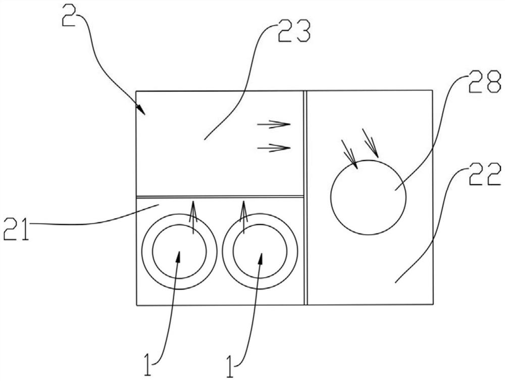
The invention provides a tail gas treatment device. The tail gas treatment device comprises a gas inlet pipeline, a spraying box and a spraying mechanism. The spraying box is provided with a sprayingcavity; the air inlet pipeline is connected into the spraying cavity and extends towards a bottom plate of the spraying cavity; the spraying mechanism is provided with at least two spraying heads which are vertically arranged at intervals, and the spraying heads are all located in the air inlet pipeline. The spray header is directly arranged in the gas inlet pipeline of the waste gas, so that theworking surface of the spray header is limited in the gas inlet pipeline, the water mist density in a spray area is improved, the waste gas is fully sprayed in the pipe, and particulate matters in thewaste gas are purified. Therefore, the problems that in the prior art, after waste gas enters a spraying cavity with a larger cross section and a larger space, spraying operation is carried out, anddue to the fact that the spraying operation area is increased, spraying is insufficient, and the purification effect is reduced can be solved.

Description

Technical field[0001]The present invention relates to the field of exhaust gas treatment, in particular to an exhaust gas treatment device.Background technique[0002]In industrial production, exhaust gas and particulate matter are often discharged. Because the exhaust gas has a certain temperature and a certain flow pressure when it is discharged, some particulate matter will be discharged together with the exhaust gas. According to the different gas production equipment, the exhaust gas may contain high-temperature metal particles, sawdust, dust, paraffin, lubricating oil, etc.[0003]Existing waste gas treatment is a more common spray box. The spray box has an atomization chamber. The gas pipeline enters the exhaust gas into the atomization chamber. There are multiple spray heads in the atomization chamber to mist the exhaust gas. Spray washing, so as to purify the particulate matter in the exhaust gas. However, the large volume of the atomization chamber results in a low density of ...

Claims


Application Information

Patent Timeline
IPC IPC(8): B01D47/06B01D50/00B01D53/14B01D53/18B01D53/26
CPCB01D47/06B01D53/18B01D53/14B01D53/263B01D2258/02B01D50/60Y02A50/2351
Inventor 张进森
Owner 厦门艾涂仕环保设备有限公司
Learn More