Rare earth ore block crushing equipment
A kind of crushing equipment and rare earth ore technology, which is applied in the field of rare earth ore block crushing equipment, and can solve the problems of long crushing time and too crushed rare earth ore
- Summary
- Abstract
- Description
- Claims
- Application Information
AI Technical Summary
Problems solved by technology
Method used
Image
Examples
Embodiment 1
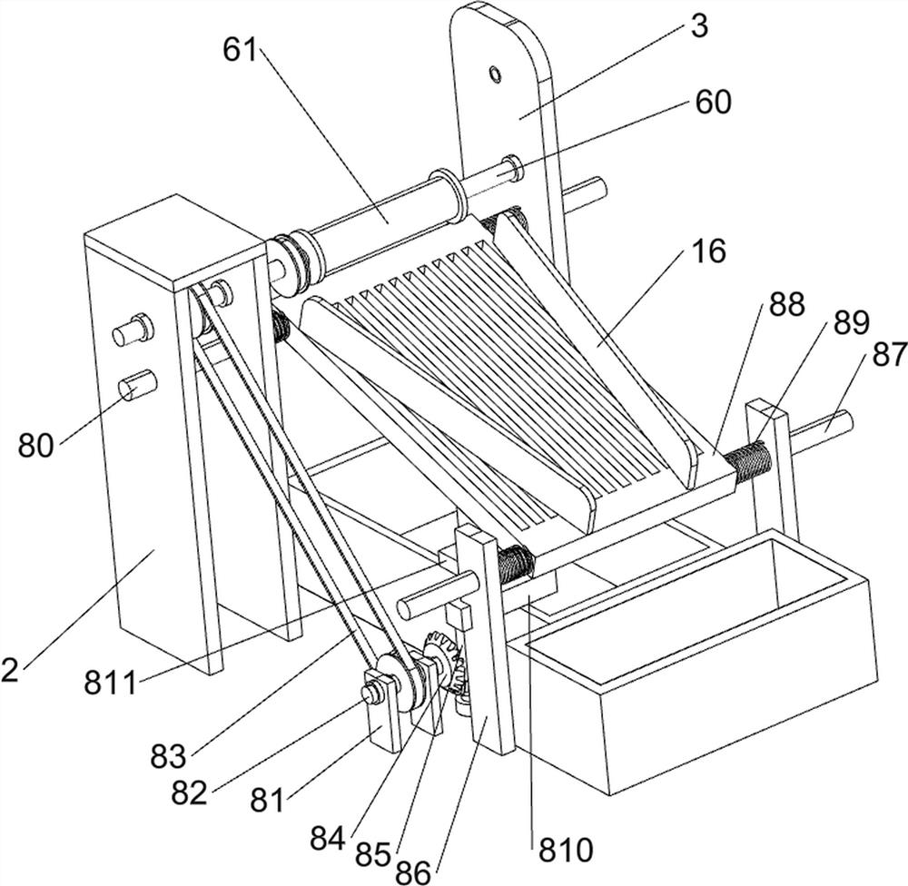
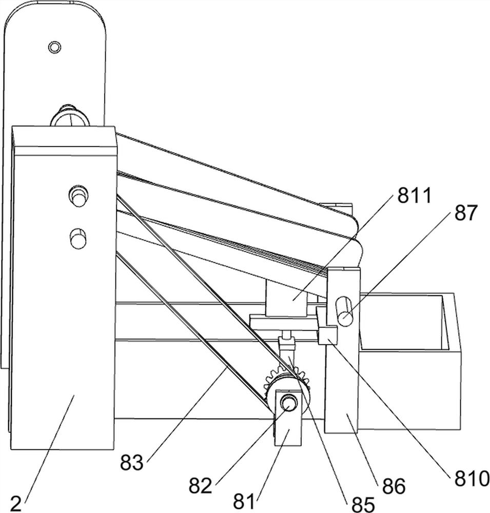
[0025] A rare earth ore block crushing equipment, such as figure 1 As shown, it includes a base plate 1, a first bracket 2, a first support plate 3, a second support plate 4, a third support plate 5, a crushing mechanism 6, a conveying mechanism 7, and a screening mechanism 8. There is a first bracket 2, a first support plate 3 is provided in the middle of the upper rear side of the bottom plate 1, a second support plate 4 is arranged symmetrically front and back on the left side of the upper part of the bottom plate 1, and a third support plate 5 is provided in the middle of the upper front side of the bottom plate 1, A crushing mechanism 6 is provided between the first bracket 2 and the first support plate 3 , a conveying mechanism 7 is provided between the second support plate 4 and the third support plate 5 , and a screening mechanism 8 is provided on the upper right side of the bottom plate 1 .
[0026] When the user needs to crush the rare earth ore, this equipment can b...
Embodiment 2
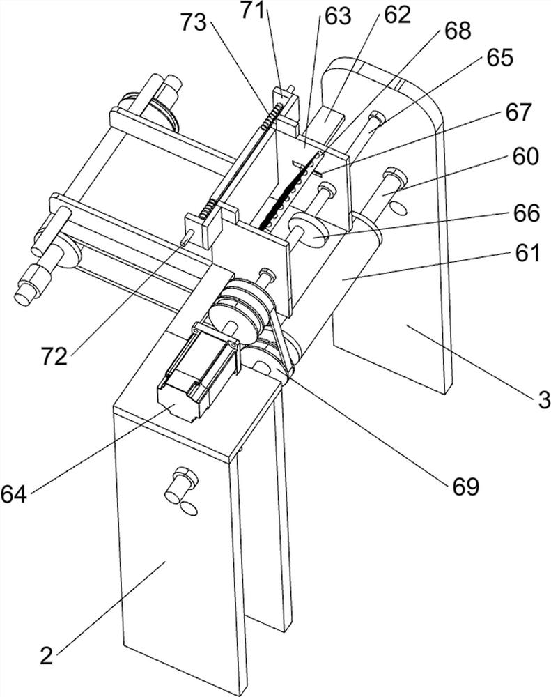
[0028] On the basis of Example 1, such as figure 2 , image 3 , Figure 4 , Figure 5 and Figure 6As shown, the crushing mechanism 6 includes a first rotating shaft 60, a first conveyor belt 61, a connecting plate 62, a crushing box 63, a servo motor 64, a second rotating shaft 65, an eccentric wheel 66, a first spring 67, a crushing block 68 and a first Pulley assembly 69, between the first bracket 2 and the first support plate 3 and between the second support plate 4 on both sides are all rotatably provided with a first rotating shaft 60, and a first rotating shaft 60 is connected between the first rotating shaft 60 on both sides. Conveyor belt 61, connecting plate 62 is arranged between the first bracket 2 and the first supporting plate 3, and crushing box 63 is connected between the connecting plates 62 on both sides, and the upper part of the first bracket 2 is provided with a servo motor 64, and the servo motor 64 A second rotating shaft 65 is connected between the...
Embodiment 3
[0035] On the basis of Example 2, such as Figure 7 As shown, it also includes the sixth rotating shaft 9, the fourth pulley assembly 10, the second conveyor belt 11, the push block 12, the second bracket 13, the fifth support plate 14 and the first protective plate 15, and the upper left side of the bottom plate 1 is provided with The second support 13, the left and right sides of the second support 13 are symmetrically provided with two pairs of the fifth support plates 14, and the second support plates 4 on both sides are connected in rotation with the fifth support plates 14 on the left side. There is a sixth rotating shaft 9, a second conveyor belt 11 is connected between the sixth rotating shafts 9 on both sides, and a first protective plate 15 is connected between the fifth support plates 14 on both sides, and the first protective plates 15 on both sides are respectively located On both sides of the second conveyor belt 11 , a plurality of pushing blocks 12 are evenly s...
PUM
 Abstract
Description
Claims
Application Information
 - R&D
- Intellectual Property
- Life Sciences
- Materials
- Tech Scout
- Unparalleled Data Quality
- Higher Quality Content
- 60% Fewer Hallucinations
Browse by: Latest US Patents, China's latest patents, Technical Efficacy Thesaurus, Application Domain, Technology Topic, Popular Technical Reports.
© 2025 PatSnap. All rights reserved.Legal|Privacy policy|Modern Slavery Act Transparency Statement|Sitemap|About US| Contact US: help@patsnap.com


