Full-automatic reinforcing steel bar cut-to-length shearing device

A fixed-length cutting and fully automatic technology, applied in the field of steel bar processing, can solve the problems of edge wear, material waste, and high cost of use

Active Publication Date: 2021-01-01
广西吉长旺新材料科技有限公司
View PDF8 Cites 2 Cited by
  • Summary
  • Abstract
  • Description
  • Claims
  • Application Information

AI Technical Summary

Problems solved by technology

[0004] The above-mentioned patents have the following disadvantages: when the cutting tool is re-cut, the cutting edge will be worn, and the entire cutting tool needs to be replaced as long as the cutting edge wears to a certain extent. The material will cause waste, high cost of use

Method used


Image

  • Full-automatic reinforcing steel bar cut-to-length shearing device
  • Full-automatic reinforcing steel bar cut-to-length shearing device
  • Full-automatic reinforcing steel bar cut-to-length shearing device

Examples


Embodiment 1

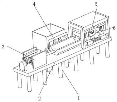
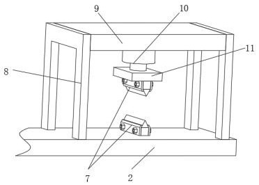
[0038] A fully automatic steel bar fixed-length shearing device, such as Figure 1-4 As shown, it includes a workbench 2 fixed on the ground by a leg-1, and the top outer wall of the workbench 2 is provided with a feeding mechanism 3, a feeding mechanism 4 and a shearing mechanism 5 in sequence, and the shearing mechanism 5 includes Two sets of cutter assemblies 7 and hydraulic cylinders 10, the top outer wall of the workbench 2 is fixed with two gantry frames 8 by bolts, the top outer wall of the gantry frame 8 is fixed with a top plate 9 by bolts, and the hydraulic cylinder 10 is fixed on the top plate 9 by bolts On the bottom outer wall of the hydraulic cylinder 10, the outer wall of the telescopic end of the hydraulic cylinder 10 is fixed with a lifting frame 11 by bolts, wherein one set of cutter assemblies 7 is fixedly installed on the bottom outer wall of the lifting frame 11, and the other set of cutter assemblies 7 is fixed on the bottom outer wall of the lifting frame...

Embodiment 2

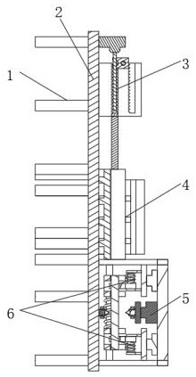
[0042] A fully automatic steel bar fixed-length shearing device, such as figure 1 , 7 As shown, in order to solve the safety problem; this embodiment makes the following improvements on the basis of Embodiment 1: the top outer wall of the workbench 2 is provided with two sets of fixed buffer mechanisms 6 that are symmetrical to the shearing mechanism 5, and the fixed Buffering mechanism 6 comprises fixed claw one 35 and fixed claw two 36, and the inner wall of described fixed claw one 35 and fixed claw two 36 is all provided with V-shaped groove 34, and the opposite side outer walls of two described gantry frames 8 are fixed by bolts Slide bar one 32 is arranged, and described fixed claw one 35 is slidably connected on the outer wall of slide bar one 32, and the opposite side outer wall of two described fixed claw one 35 is welded with spring one 33, and the bottom outer wall of described top plate 9 passes through Cylinder 40 is fixed by bolts, and the piston connecting rod ...


PUM


Abstract

The invention discloses a full-automatic reinforcing steel bar cut-to-length shearing device, relates to the technical field of reinforcing steel bar processing, and aims to solve the problem of service life of a tool. The full-automatic reinforcing steel bar cut-to-length shearing device specifically comprises a worktable fixed to the ground through a supporting leg I, wherein a feeding mechanism, a loading mechanism and a shearing mechanism are successively arranged on the outer wall of the top of the worktable; the shearing mechanism comprises two tool assemblies and a hydraulic cylinder, two portal frames are fixed to the outer wall of the top of the worktable through bolts, a top plate is fixed to the outer walls of the tops of the portal frames through bolts, the hydraulic cylinder is fixed to the outer wall of the bottom of the top plate through bolts, a lifting rack is fixed to the outer wall of a telescopic end of the hydraulic cylinder through bolts, and one tool assembly isfixedly mounted on the outer wall of the bottom of the lifting rack. By arranging the tools in normal triangular prism structures and processing a cutting edge in each edge, when one edge is worn, cutting edges of other edges still can perform shearing work, so that the service life of the single tool is prolonged and the using cost is lowered.

Description

technical field [0001] The invention relates to the technical field of steel bar processing, in particular to an automatic steel bar fixed-length shearing device. Background technique [0002] When the steel bar is initially formed and transported, it is generally a long steel bar segment, but in actual use, it needs to be cut to the required length by a shearing device, and then used, and the core of the steel bar shearing device is The part is the shearing tool, which is a wearing part and needs to be replaced regularly. How to reduce the number of tool replacements, thereby reducing the cost of use, is the problem that the present invention aims to solve. [0003] After retrieval, the Chinese patent publication number is CN106623686A, which discloses a steel bar shearing device, including a first guide roller and a second guide roller for driving steel bar feeding, a steel bar straightening machine, and a fixed-length shearing mechanism and the blanking mechanism, the fi...

Claims


Application Information

Patent Timeline
Patent Type & Authority Applications(China)
IPC IPC(8): B21F11/00B21F23/00
CPCB21F11/00B21F23/00
Inventor 张光伟陈积光张光胜
Owner 广西吉长旺新材料科技有限公司
Why Eureka
Try Eureka