Aircraft manufacturing material processing device

A material processing and aircraft technology, applied in the field of aircraft, can solve problems such as debris splashing on the ground, inconvenient ground cleaning, etc.

Pending Publication Date: 2021-01-01
莘志强
View PDF0 Cites 0 Cited by
  • Summary
  • Abstract
  • Description
  • Claims
  • Application Information

AI Technical Summary

Problems solved by technology

[0004] The purpose of the present invention is to solve the shortcomings of debris splashing and scattering on the ground in the prior art, which is inconvenient to clean the ground, and proposes a material processing device for aircraft manufacturing

Method used


Image

  • Aircraft manufacturing material processing device
  • Aircraft manufacturing material processing device
  • Aircraft manufacturing material processing device

Examples


Embodiment 1

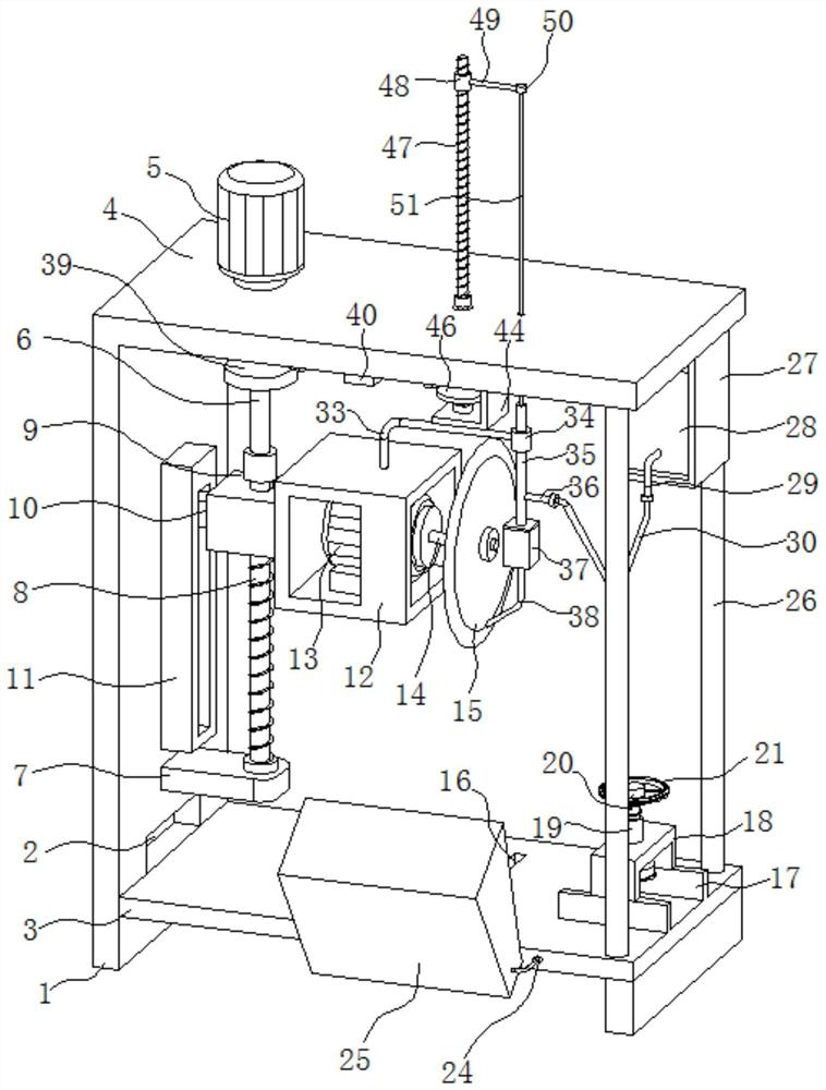
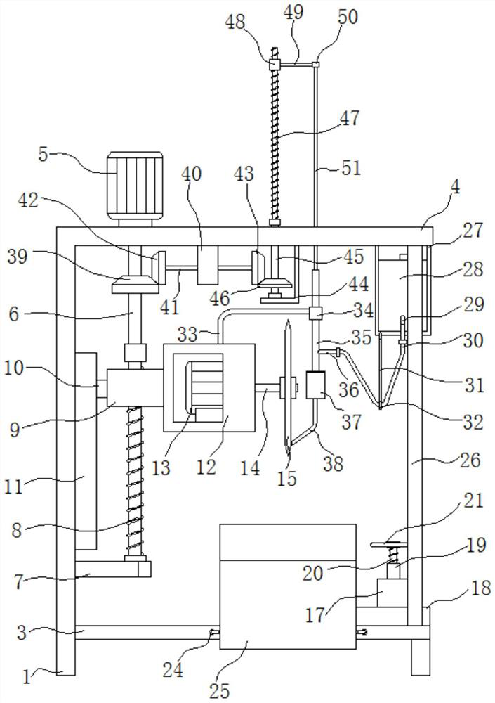
[0021] refer to Figure 1-4 , a material processing device for aircraft manufacturing, comprising a support plate 1, the bottom end of the support plate 1 is connected with anti-skid lines, the support plate 1 is connected with a bottom plate 3, and the side of the bottom surface of the bottom plate 3 away from the support plate 1 is connected with a support Feet, the base plate 3 is provided with a strip hole 2, the inner bottom of the strip hole 2 is flush with the upper surface of the base plate 3, the upper end of the support plate 1 is connected with a top plate 4, and the upper end of the top plate 4 is connected with a first motor 5, The first motor 5 is connected to an external power supply through a wire, and the output end of the first motor 5 is driven to be connected with a first rotating shaft 6, and one end of the first rotating shaft 6 runs through the top plate 4, and one end of the first rotating shaft 6 is connected with a first reciprocating screw 8 for suppo...

Embodiment 2

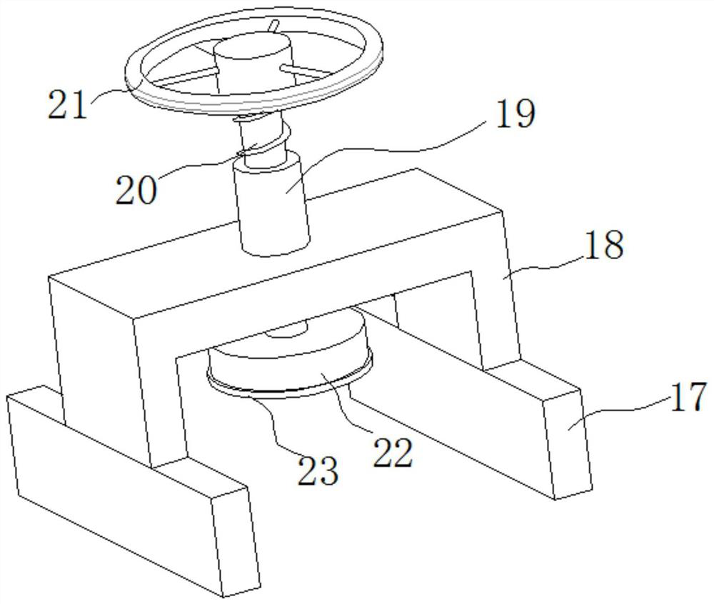
[0027] When the blade 15 cuts the metal plate, the temperature at the metal plate otch is higher, which easily causes the metal plate otch to be deformed due to the high temperature, and the debris produced in the cutting process has a higher temperature equally, and the collection box 25 collects the debris When the crumbs are removed, the temperature of itself will rise, which will easily damage the inner elastic cloth pad. Refer to Figure 1-4 , as another preferred embodiment of the present invention, the difference from Embodiment 1 is that the side of the lower surface of the top plate 4 away from the support plate 1 is connected with a second fixing frame 27, and the second fixing frame 27 is connected with a liquid storage tank 28 The bottom end of one side of the liquid storage tank 28 is connected with a first metal pipe 29, and one end of the first metal pipe 29 is connected with a hose 30, and the second fixed frame 27 is connected with a first connecting rod 31, an...

Embodiment 3

[0029] Because the blade 15 only needs to cool down when the metal plate is cut, and the outlet of the metal elbow 38 has been releasing coolant, resulting in waste of coolant, refer to Figure 1-4 , as another preferred embodiment of the present invention, the difference from Embodiment 2 is that the first rotating shaft 6 is connected with a first helical gear 39, the lower surface of the top plate 4 is connected with a fixed block 40, and the rotatable connection on the fixed block 40 There is a third rotating shaft 41, and the third rotating shaft 41 runs through the fixed block 40. One end of the third rotating shaft 41 is connected with a second helical gear 42, and the second helical gear 42 meshes with the first helical gear 39. The number of teeth of the first helical gear 39 is greater than The number of teeth of the second helical gear 42, the other end of the third rotating shaft 41 is connected with the third helical gear 43, the lower surface of the top plate 4 is...


PUM


Abstract

The invention relates to the technical field of aircrafts, in particular to an aircraft manufacturing material processing device which comprises a supporting plate. A second motor is connected onto afirst fixing frame; a second rotating shaft is connected to the output end of the second motor; a blade is connected to one end of the second rotating shaft; a cutting hole is formed in the position,located under the blade, on a bottom plate; when the blade moves to the lowest end, the bottom end of the blade can be inserted into the cutting hole; two parallel limiting plates are connected to theside, away from a strip-shaped hole, of the upper end of the bottom plate; fixing mechanisms are connected to the upper ends of the limiting plates; two parallel fixing bases are connected onto the bottom plate; a collecting box is connected between the two fixing bases; and an elastic cloth pad is connected into the collecting box. According to the aircraft manufacturing material processing device provided by the invention, the collecting box collects chippings generated in the cutting process, and the collision strength between the chippings and the collecting box is reduced through the elastic cloth pad in the collecting box, so that the probability that chippings pop out of the collecting box is reduced; and the collecting box collects the chippings, so that the number of the ground chippings is reduced, and the convenience in sweeping is realized.

Description

technical field [0001] The invention relates to the technical field of aircraft, in particular to a material processing device for aircraft manufacturing. Background technique [0002] Aircraft is an instrumental flying object that is manufactured by humans, can fly off the ground, fly in space and is controlled by humans in the atmosphere or in the space outside the atmosphere (space). Those that fly in the atmosphere are called aircraft, and those that fly in space are called spacecraft. They rely on the static buoyancy of the air or the aerodynamic force generated by the relative motion of the air to fly into the air. Those that fly in space are called spacecraft, such as artificial earth satellites, Manned spacecraft, space probes, space shuttles, etc., are propelled by the launch vehicle to obtain the necessary speed to enter space, and then rely on inertia to make orbital motions similar to celestial bodies. [0003] In the manufacturing process of the aircraft, metal...

Claims


Application Information

Patent Timeline
Patent Type & Authority Applications(China)
IPC IPC(8): B23Q5/10B23Q5/28B23Q11/00
CPCB23Q5/10B23Q5/28B23Q11/0042
Inventor 不公告发明人
Owner 莘志强
Why Eureka
Try Eureka