Automatic centering clamping mechanism with self-locking function

An automatic centering and clamping mechanism technology, applied in the direction of workpiece clamping devices, manufacturing tools, etc., can solve problems such as difficult to ensure the position, difficult to twist the handwheel, and difficult to center, so as to ensure that the compression is in place and good self-locking performance effect

Pending Publication Date: 2021-01-01
江苏赛仑特智能装备有限公司 +1
View PDF0 Cites 1 Cited by
  • Summary
  • Abstract
  • Description
  • Claims
  • Application Information

AI Technical Summary

Problems solved by technology

[0002] The existing centering clamping mechanism is manual clamping, and the clamping is performed by manually turning the screw to transmit the force to the pressure plate to achieve compression. This method is difficult to ensure that the clamping is in place when a large pressure is required.
The centering is also achieved by manually rotating the handwheel and pushing the top block through the screw to achieve the centering of the workpiece. This method requires a lot of thrust for larger workpieces, and it is difficult to manually twist the handwheel. It is difficult to center and it is difficult to ensure that the clamping is in place.
The centering and clamping time of the existing mechanism is long, the manual tightening force is large and it is difficult to ensure that it is in place, and the qualified rate of the product cannot be guaranteed
Clamping depends entirely on the thread, which is prone to failure after long-term use

Method used


Image

  • Automatic centering clamping mechanism with self-locking function
  • Automatic centering clamping mechanism with self-locking function
  • Automatic centering clamping mechanism with self-locking function

Examples


Embodiment Construction

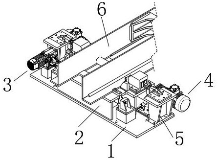
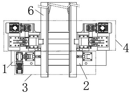
[0021] Such as Figure 1-6 It is a structural schematic diagram of the present invention, a self-locking automatic centering clamping mechanism, including a centering clamping base 1, a support plate 2 is welded on the centering clamping base 1, and the outer end of the support plate 2 has There are clamping assemblies 4 on both sides of the centering assembly 3 and the support plate 2 .

[0022] When this self-locking automatic centering clamping mechanism is in use, the centering assembly 3 of the device will center the workpiece 6 placed on the support plate 2, that is, to place the workpiece on the support plate 2 In order to ensure the accuracy of machining, after the centering is completed, the workpiece 6 is clamped by the clamping assembly to facilitate subsequent processing.

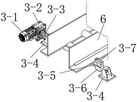
[0023] According to another embodiment of the present invention, it further includes that the centering assembly 3 includes a centering motor 3-1, and a centering reducer 3-2 is connected to th...


PUM


Abstract

The invention relates to the technical field of machining, in particular to an automatic centering clamping mechanism with a self-locking function. The automatic centering clamping mechanism with theself-locking function comprises a centering clamping machine base, a supporting plate is welded to the centering clamping machine base, a centering assembly is arranged at the outer end of the supporting plate, and clamping assemblies are arranged on the two sides of the supporting plate. Power of the automatic centering clamping mechanism with the self-locking function is completely from a motor,the power is transmitted to a connecting rod mechanism through a worm gear and a worm in the clamping process, then the connecting rod mechanism transmits the power to a pressing wedge block, a workpiece is pressed through the pressing wedge block, the worm gear and the worm have good self-locking performance, the self-locking purpose is achieved, the connecting rod mechanism realizes self-locking through a dead point and ensures that the pressing force becomes larger and larger, enough force is provided, and in-place pressing is ensured.

Description

technical field [0001] The invention relates to the technical field of machining, in particular to an automatic centering clamping mechanism with self-locking. Background technique [0002] The existing centering clamping mechanism is manual clamping, and the clamping is performed by manually turning the screw rod to transmit the force to the pressure plate to achieve compression. This method is difficult to ensure that the clamping is in place when a large pressure is required. The centering is also achieved by manually rotating the handwheel and pushing the top block through the screw to achieve the centering of the workpiece. This method requires a large thrust for larger workpieces, and it is difficult to manually twist the handwheel. It is difficult to center and it is difficult to ensure that the clamping is in place. . The centering and clamping time of the existing mechanism is long, the manual screwing force is large and it is difficult to ensure that it is in plac...

Claims


Application Information

Patent Timeline
Patent Type & Authority Applications(China)
IPC IPC(8): B25B11/00
CPCB25B11/00
Inventor 张浩杨杰于海武刘春屈婧
Owner 江苏赛仑特智能装备有限公司
Why Eureka
Try Eureka