Al technical title is built by PatSnap Al team. It summarizes the technical point description of the patent document.
A flexible joint and variable stiffness technology, applied in the field of robots, can solve the problems of difficult transmission accuracy, complex cam groove design, short working life, etc., and achieve the effects of low cost, easy replacement and simple processing
Active Publication Date: 2017-08-18
HEBEI UNIV OF TECH
View PDF8 Cites 11 Cited by
Summary
Abstract
Description
Claims
Application Information
AI Technical Summary
This helps you quickly interpret patents by identifying the three key elements:
Problems solved by technology
Method used
Benefits of technology
Problems solved by technology
However, its structure also has certain shortcomings. There will be friction during the sliding process of the cam along the cam groove, resulting in energy loss and low efficiency.
The stress on the cam and the cam connection is relatively large, and the working life is short
The characteristic of variable stiffness is determined by the cam groove. The design of the cam groove is relatively complicated, which makes it difficult to guarantee the transmission accuracy.
Method used
Image
Click on the blue label to locate the original text in one second.
Reading with bidirectional positioning of images and text.
Examples
Embodiment 1
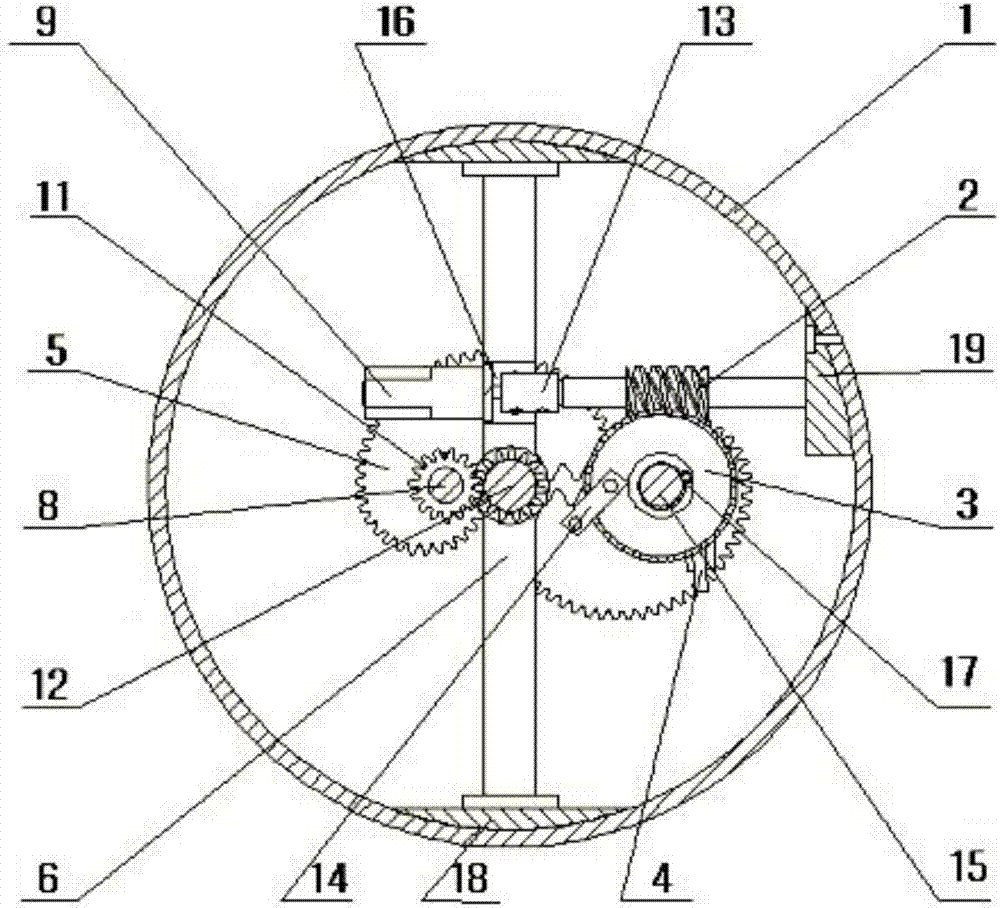
[0032] The rotary variable stiffness flexible joint in this embodiment includes a drive plate 1, an end cover 10, a torsion spring 4, a special-shaped gear set 5, a standard gear set 11, a shaft 15, a shaft 2 8, an output shaft 12, a shaft end fixing frame 6, Worm 2, worm gear 3, DC gear motor 9, coupling 13, connecting plate 14, worm fixing block 19, retaining spring 17, motor mount 16, fixing block 18 and bearing seat 7;
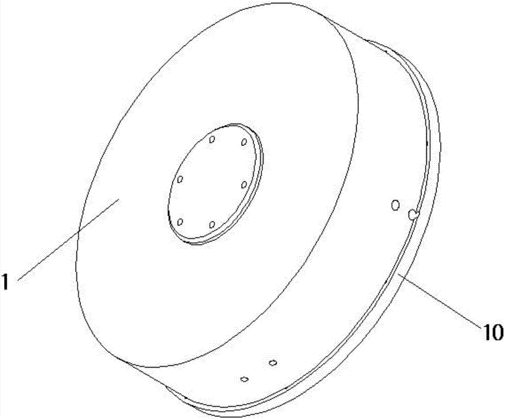
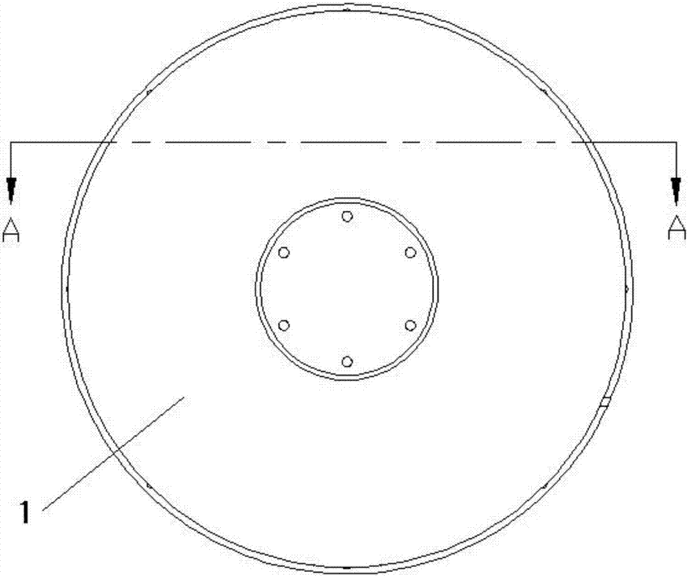
[0033] The drive disc 1 is fixed to the end cover 10, and the end of the drive disc 1 is directly connected to the external motor through the reducer as the input of the flexible joint; the drive disc 1 is provided with a bearing seat 7 and a shaft end fixing frame 6, and the bearing seat 7 It has an integrated structure with the drive plate 1, and the drive plate 1 and the end cover 10 are connected by bolts as a joint shell; the two ends of the shaft end fixing frame 6 are fixed on the drive plate 1 through the fixing block 18, and the end cover 10 and th...
PUM
Abstract
The invention relates to a rotating type varying stiffness flexible joint. The joint is characterized by comprising a driving disc, an end cover, a torsional spring, a special-shaped gear set, a standard gear set, a first shaft, a second shaft, an output shaft, a shaft end fixed frame, a worm, a worm gear, a direct-current speed reduction motor, a coupler, a connecting plate, a worm fixing block, a clamping spring, a motor mounting base, fixing blocks and a bearing pedestal; the driving disc is fixed to the end cover, the end of the driving disc is connected with an outer motor directly through a speed reducer to serve as input of the flexible joint, the bearing pedestal and the shaft end fixing frame are arranged in the driving disc, the bearing pedestal and the driving disc are of an integral structure, the driving disc and the end cover are connected through a bolt to serve as a shell of the joint, the two ends of the shaft end fixing frame are fixed to the driving disc through the fixing blocks, the output shaft is fixedly arranged between the end cover and the shaft end foxing frame through a deep groove ball bearing, and the output shaft is connected with an outer component; the first shaft and the second shaft are fixed to the driving disc and the end cover through the deep groove ball bearing and the bearing pedestal.
Description
technical field [0001] The invention relates to the technical field of robots, in particular to a rotary variable stiffness flexible joint. Background technique [0002] In recent years, articulated robots have been widely used in earthquake relief, medical treatment, industrial production and many other fields due to their flexible activities, simple structure, strong environmental adaptability and large working space. The rotary joint is one of the important components of the robot, which is of great significance to the stability and accuracy of the robot's movement. Traditional robot joints adopt rigid design, and the movement speed and precision have reached a high level. However, with the continuous popularization of robots, in the face of new tasks, rigid joints can no longer meet the requirements: working in places with many obstacles or other complex In an unknown environment, rigid robots are vulnerable to reduced accuracy or damage due to unknown collisions. For h...
Claims
Application Information
Patent Timeline
Application Date:The date an application was filed.
Publication Date:The date a patent or application was officially published.
First Publication Date:The earliest publication date of a patent with the same application number.
Issue Date:Publication date of the patent grant document.
PCT Entry Date:The Entry date of PCT National Phase.
Estimated Expiry Date:The statutory expiry date of a patent right according to the Patent Law, and it is the longest term of protection that the patent right can achieve without the termination of the patent right due to other reasons(Term extension factor has been taken into account ).
Invalid Date:Actual expiry date is based on effective date or publication date of legal transaction data of invalid patent.